Reproducing system and corresponding information recording medium having wobbled land portions

a technology of information recording medium and recording system, applied in the field of information recording medium, can solve the problems of excessive loss of information, damage to information recorded in adjacent grooves, and excessive cross erase phenomenon, and achieve the effect of reducing cross erase and increasing density

Inactive Publication Date: 2007-06-14
JVC KENWOOD CORP
View PDF11 Cites 14 Cited by
  • Summary
  • Abstract
  • Description
  • Claims
  • Application Information

AI Technical Summary

Benefits of technology

[0023] Accordingly, in consideration of the above-mentioned problems of the prior art, an object of the present invention is to provide an information recording medium that is reduced in cross erase and can be recorded in higher density, and an reproducing apparatus for reproducing information recorded in the information recording medium with making the information recording medium move relatively.

Problems solved by technology

The inventors founded a problem such that a cross erase phenomenon was extremely noticeable.
If such a cross erase phenomenon occurs, as mentioned above, information recorded in an adjacent groove is damaged.
In case of an information system having larger capacity, an amount of lost information becomes excessively large.
Consequently, affection to a user is enormous.
However, there is existed a problem such that recording capacity of an information recording medium will decrease and a merit of the information recording medium having a potential of recording in higher density will decline if such an information recording method is conducted.

Method used


Image

  • Reproducing system and corresponding information recording medium having wobbled land portions
  • Reproducing system and corresponding information recording medium having wobbled land portions
  • Reproducing system and corresponding information recording medium having wobbled land portions

Examples


first embodiment

[0069] With referring to FIG. 1, a basic configuration of an information recording medium according to the present invention will be explained. An information recording medium according to a first embodiment of the present invention is such an information recording medium that at least one of recording and reproducing is conducted through an optical method. Actually, it is such an information recording medium as a phase change recording type information recording medium, a dye type information recording medium, a magneto-optical type information recording medium or a light assist magnetic type information recording medium.

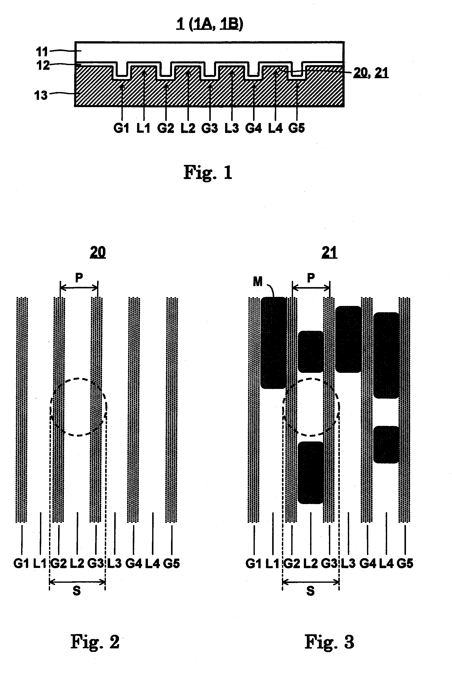
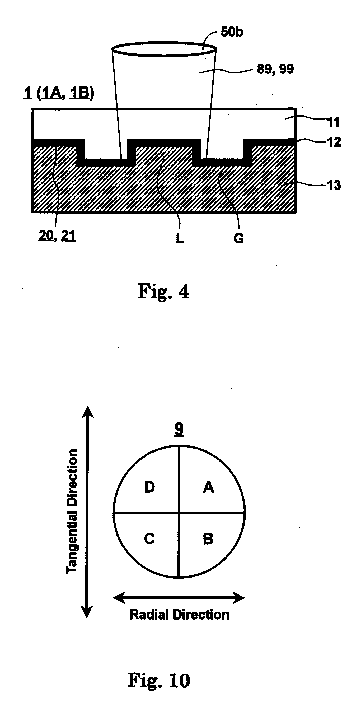
[0070]FIG. 1 is a cross sectional view of an information recording medium according to a first embodiment of the present invention. In FIG. 1, an information recording medium 1 according to the present invention is at least composed of a light transmitting layer 11, a recording layer 12, and a substrate 13 formed with a microscopic pattern 20. They are formed sequ...

second embodiment

[0262]FIG. 29 is a cross sectional view of an information recording medium according to a second embodiment of the present invention. In FIG. 29, an information recording medium 2 is identical to the information recording medium 1 shown in FIG. 1 except for the light transmitting layer 11, so that details of the same components will be omitted. As shown in FIG. 29, the light transmitting layer 11 of the information recording medium 1 is divided into two layers; a light transmitting layer 11a and an adhesive light transmitting layer 11b, wherein the light transmitting layer 11a is similar to the light transmitting layer 11 as mentioned above. The adhesive light transmitting layer 11b is a layer for adhering the light transmitting layer 11a on the recording layer 12 firmly, and transmits more than 70% of light having a wavelength λ, desirably more than 80%.

[0263] With respect to a material of the adhesive light transmitting layer 11a, an adhesive or cohesive resin such as thermosetti...

third embodiment

[0265]FIG. 30 is a cross sectional view of an information recording medium according to a third embodiment of the present invention. In FIG. 30, an information recording medium 3 is identical to the information recording medium 1 shown in FIG. 1 except for the substrate 13, so that details of the same components will be omitted. As shown in FIG. 30, the substrate 13 shown in FIG. 1 is replace with a substance of two-layer structure; a substrate 13a and a resin layer 14.

[0266] With respect to a material of the resin layer 14, such resins as thermosetting resins, various energy ray curable resins including UV ray curable resins, visible radiation curable resins and electron beam curable resins, moisture curable resins, plural liquid mixture curable resins and thermoplastic resins containing solvent can be used. Reproducing light never reaches to the resin layer 14, so that there is existed no limitation in transmittance.

[0267] Further, a thickness of the resin layer 14 is desirable ...


PUM

PropertyMeasurementUnit
reflectivityaaaaaaaaaa
wavelengthaaaaaaaaaa

Abstract

An information recording medium is at least composed of a substrate having a microscopic pattern constituted by a continuous substrate of grooves formed with a groove portion and a land portion alternately, a recording layer formed on the microscopic pattern for recording information, and a light transmitting layer formed on the recording layer. The microscopic pattern is formed with satisfying a relation of P≦λ / NA, wherein P is a pitch of the land portion or the groove portion, λ is a wavelength of reproducing light for reproducing the recording layer, and NA is a numerical aperture of an objective lens. The land portion is formed with wobbling so as to be parallel with each other for both sidewalls of the land portion. An auxiliary information based on data used supplementally when recording the information and a reference clock based on a clock used for controlling a recording speed when recording the information is recorded alternately. Information is recorded in the recording layer corresponding to only a land portion by at least either one change of reflectivity difference and refractive index difference in the recording layer so as to be more than 5% for reflectivity and so as to be more than 0.4 for modulated amplitude of signal recording.

Description

CROSS-REFERENCE TO RELATED APPLICATIONS [0001] This application is a Continuation of co-pending Application Ser. No. 10 / 419,149, filed on Apr. 21, 2003, and for which priority is claimed under 35 U.S.C. § 120; and this application claims priority of Application No. 2002-117555 filed in Japan on Apr. 19, 2002 under 35 U.S.C. § 119; this application also claims priority of Application No. 2002-141286 filed in Japan on May 16, 2002 under 35 U.S.C. § 119; this application also claims priority of Application No. 2002-160129 filed in Japan on May 31, 2002 under 35 U.S.C. § 119; this application also claims priority of Application No. 2002-123612 filed in Japan on Apr. 25, 2002 under 35 U.S.C. § 119; and this application claims priority of Application No. 2002-148781 filed in Japan on May 23, 2002 under 35 U.S.C. § 119; the entire contents of all are hereby incorporated by reference.BACKGROUND OF THE INVENTION [0002] 1. Field of the Invention [0003] The present invention relates to an info...

Claims


Application Information

Patent Timeline
Patent Type & Authority Applications(United States)
IPC IPC(8): G11B27/22G11B7/24G11B5/855G11B7/0045G11B7/007G11B11/105
CPCG11B5/855G11B7/00455G11B7/00736G11B7/24012G11B7/24079G11B7/24082G11B11/10578G11B11/10584G11B7/24097
Inventor KONDO, TETSUYAOISHI, KENJI
Owner JVC KENWOOD CORP
Why Eureka
Try Eureka