Method for controlling foaming of slag in an electric arc furnace

a technology of electric arc furnace and foaming, which is applied in the direction of electric furnace, lighting and heating apparatus, furnace, etc., can solve the problems of electrode column jerk, electrode column breaking and falling into the furnace, and impurity added to the molten steel, etc., and achieve the effect of stabilizing the ar

Inactive Publication Date: 2007-06-14
GRAFTECH INT HLDG INC
View PDF4 Cites 22 Cited by
  • Summary
  • Abstract
  • Description
  • Claims
  • Application Information

AI Technical Summary

Benefits of technology

[0019] It is an aspect of the present invention to provide an improved method for stabilizing an arc in an electric arc furnace.

Problems solved by technology

For example, when an arc moves excessively, it can cause the electrode column from which it extends to jerk; excessive jerking of the electrode column can cause the electrode column to break and fall into the furnace.
Further, when a portion of an electrode column falls into the furnace, it becomes an added impurity to the molten steel and undesirably decreases the steel's purity level.
Additionally, erratic movement of the electrode column, which can be caused by erratic arc movement, increases power consumption and, in turn, increases furnace operational costs.
When current is applied to the electrode columns and they are lowered so as to touch the scrap metal, each electrode column eventually creates a hole in the scrap.
During this stage, there is high power consumption and a relatively long arc.
During the bore down and early meltdown stages, the operator does not actively control the arc unless it is, for example, flaring to and / or contacting the furnace sidewall and causing excessive damage to the furnace sidewall.
However, addition of a foaming agent to the slag can be detrimental to the overall performance of the system, if, for example, too much is added or if the timing is poor.
For instance, if a carbon-based foaming agent is added too soon, the carbon may not readily combine with existing oxygen in the system to form CO but rather carbon particulates may fall into the molten steel and become an added impurity.
Also, if too much foaming agent is added, it can cause the slag to foam out of the furnace undesirably.

Method used


Image

  • Method for controlling foaming of slag in an electric arc furnace
  • Method for controlling foaming of slag in an electric arc furnace
  • Method for controlling foaming of slag in an electric arc furnace

Examples


Embodiment Construction

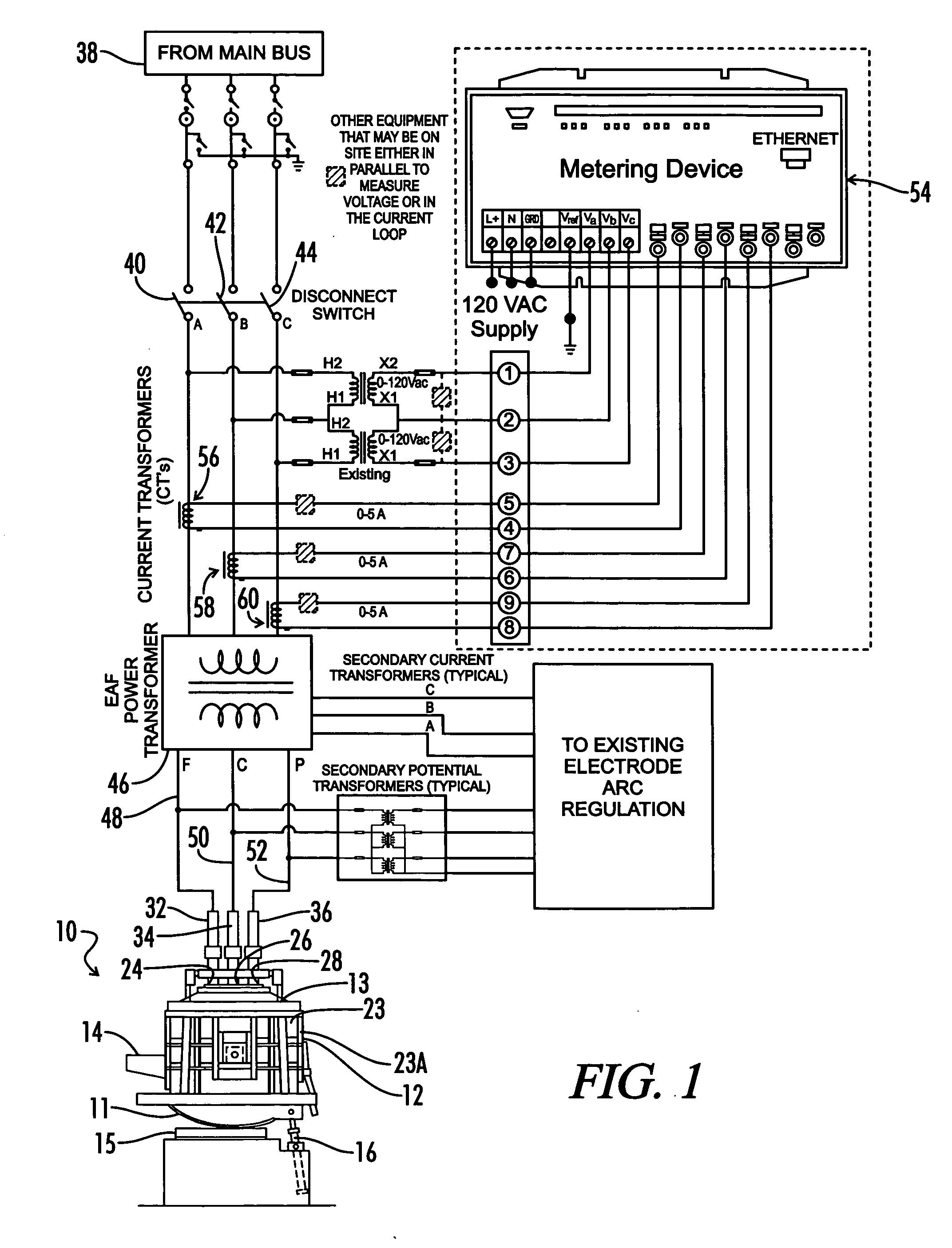
[0031] Referring in detail to FIG. 1, a conventional AC electrothermal furnace or electric arc furnace (EAF) is shown and designated by the reference numeral 10. The furnace 10 is generally cylindrical in shape and has a generally rounded bottom 11. The furnace 10 further comprises sidewall 12 extending between bottom 11 and roof 13. Although the invention herein is described with reference to an AC EAF furnace, the invention may also be used with a DC EAF furnace with a different electrical arrangement. In either case, the bottom 11 is refractory lined and the sidewall 12 is generally refractory lined to above the slag line, that is, the level in the furnace 10 to where slag normally rises. The furnace 10 has a taphole / spout 14. The EAF 10 rests on a rocker rail 15 and is capable of being titled by hydraulic cylinders 16 to pour the molten metal from the furnace 10 through spout 14.

[0032] Water-cooled panels 23 supported by a water-cooled cage 23A extend above the slag line of sid...


PUM

PropertyMeasurementUnit
electrical energyaaaaaaaaaa
total electrical energyaaaaaaaaaa
timeaaaaaaaaaa

Abstract

A method for controlling the foaming of slag in an electric arc furnace is disclosed. The furnace comprises at least one electrode column. Current is applied to the electrode column, causing an arc to form between the tip of the electrode column and the scrap, melting the scrap. Impurities in the molten scrap metal rise to the surface forming slag. A meter determines the total harmonic distortion associated with the system. If the total harmonic distortion is greater than a predetermined set point, and the scrap metal is sufficiently molten, then a foaming agent is added thereto.

Description

BACKGROUND OF THE INVENTION [0001] 1. Technical Field [0002] The present invention relates to a method for increasing the efficiency of the operation of an electric arc furnace (EAF), and, more particularly, to controlling the foaming of slag so as to better control the arc and minimize the total harmonic distortion of the system. [0003] 2. Background Art [0004] In the steel industry, graphite electrodes are used in electrothermal furnaces, sometimes called electric arc furnaces (EAFs), to melt metals and other ingredients to form steel. A series of electrodes are joined end-to-end to form an electrode column. Heat needed to melt the metals is generated by passing current through the electrode column, which causes an arc to form between the electrode column and the metals in the furnace. Typically, the furnace comprises three electrode columns. Electrical currents in excess of seventy thousand amperes are often used. The resulting high temperature melts the metals and other ingredie...

Claims


Application Information

Patent Timeline
Patent Type & Authority Applications(United States)
IPC IPC(8): F27D17/00
CPCC21C2005/5288C21C2300/02F27B3/085F27B3/28F27D19/00F27D21/00Y02P10/20Y02P10/25
Inventor GERHAN, RONALD E.LUGO, NICOLASKURELA, THEODORE J.
Owner GRAFTECH INT HLDG INC
Why Eureka
Try Eureka