Split Francis Turbine Runner

a turbine runner and split technology, applied in the direction of propellers, propulsive elements, water-acting propulsive elements, etc., can solve the problem of easy cracking of the weld joints

Inactive Publication Date: 2007-06-14
GENERAL ELECTRIC CANADA MISSISSAUGA
View PDF1 Cites 5 Cited by
  • Summary
  • Abstract
  • Description
  • Claims
  • Application Information

AI Technical Summary

Benefits of technology

[0005] The present invention relates to a split runner for a Francis turbine comprising at least two runner segments that are adapted to be joined together along confronting surface portions thereof to form a composite runner having a crown, a band and a plurality of blades extending between and attached to the crown and the band. The improvement of the present invention relates to the confronting surface portions of the runner segments being located only along portions of the crown and portions of the band, and the confronting surface portions of the runner segments being located in between and spaced from adjacent blades of the composite runner. Since the confronting surface portions are located only along portions of the crown and portions of the band, none of the blades are split thereby eliminating welding of the blades during formation of the composite runner at the dam site. Accordingly, the composite runner does not have weld joints formed in the blades which are the more highly stressed operating parts of the runner.

Problems solved by technology

During post weld heat treatment, the weld joints are susceptible to cracking which requires reprocessing of the welded joint until no cracks in the joints are present.

Method used


Image

  • Split Francis Turbine Runner
  • Split Francis Turbine Runner

Examples


Embodiment Construction

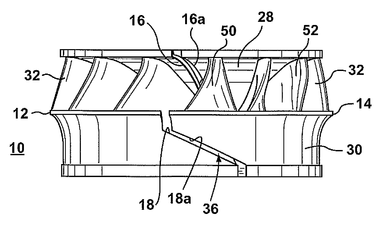
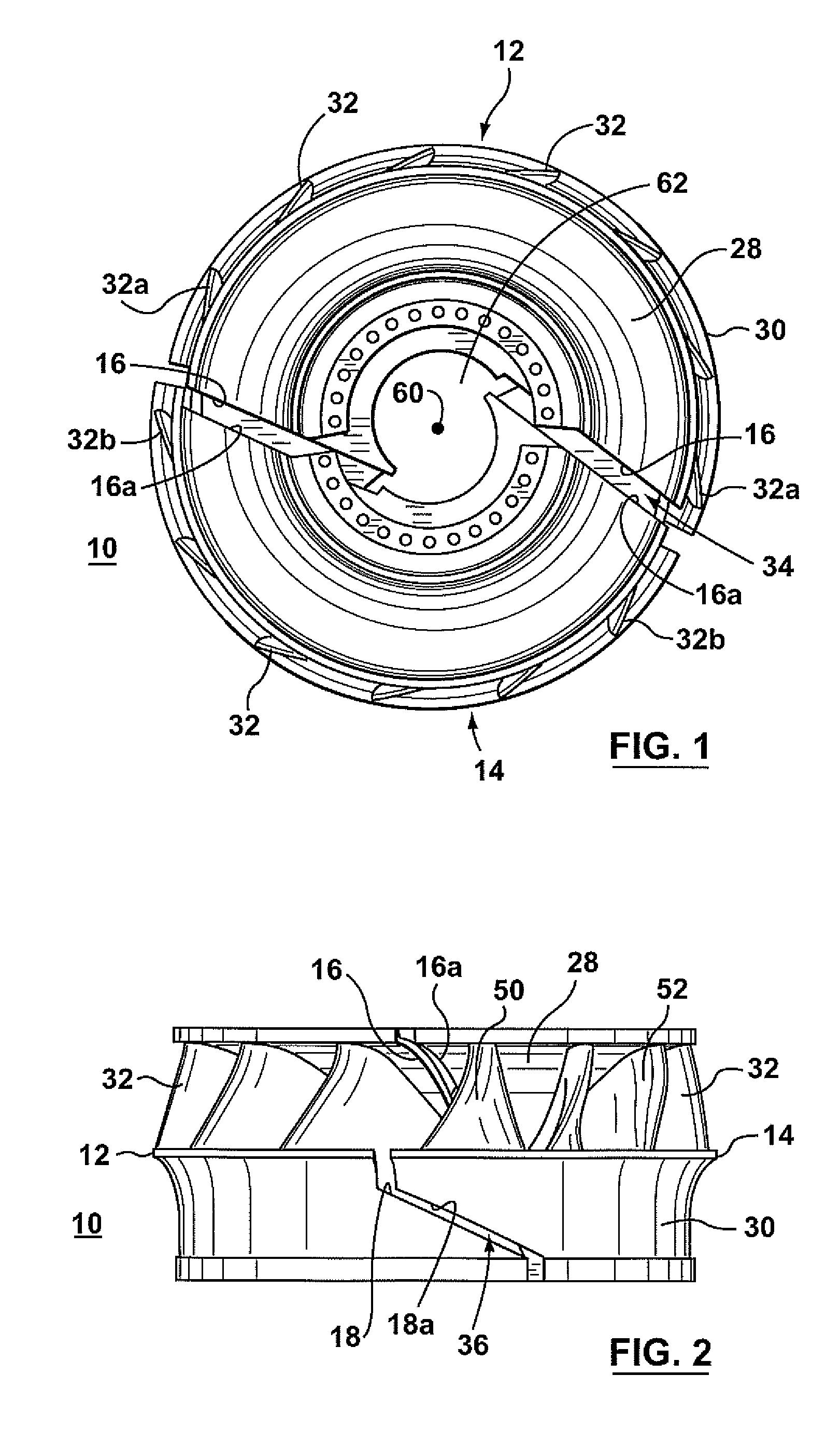
[0010] The present invention relates to Francis type turbine runners for use in water turbines and in particular it relates to a split Francis type runner 10. The split runner 10 is shown in FIGS. 1 and 2 to comprise two runner segments 12 and 14. In these Figures the two runner segments 12 and 14 are shown spaced apart. During manufacture at the manufacturing site the segments are typically machined touching each other. Also, at the dam site, the segments 12 and 14 will be in contact with each other when weld joints between the segments are made to from a composite runner.

[0011] In accordance with the present invention, these runner segments 12 and 14 are adapted to be joined together along crown confronting surface portions 16 and 16a and band confronting surface portions 18 and 18a to form a composite runner. It should be understood that the drawings show the split runner 10 in two segments and that the runner may be split into more than two segments. However, the number of segm...


PUM


Abstract

A split runner for a Francis turbine has runner segments that are adapted to be joined together along confronting surface portions thereof to form a composite runner having a crown, a band and a plurality of blades extending between the crown and the band. The confronting surface portions of the runner segments are located only along portions of the crown and portions of the band, and the confronting surface portions of the runner segments are located in between and spaced from adjacent blades of the composite runner. Since the confronting surface portions are located only along portions of the crown and portions of the band, none of the blades are split eliminating the need to weld together blades during formation of the composite runner. Accordingly, the composite runner does not have weld joints formed in the blades which are highly stressed operating parts of the runner.

Description

FIELD OF THE INVENTION [0001] The present invention relates to Francis type turbine runners and in particular to a split Francis type runner. BACKGROUND OF THE INVENTION [0002] A runners for a Francis turbine comprises a crown, band and plurality of turbine blades extending between the crown and the band. During manufacture, the blades are usually fastened to the crown and band by welds. When the diameter of the runner starts to exceed 5 meters, for example, it is known to split the turbine runner into two segments divided from each other by a plane passing along the axis of the runner so as to permit the runner to be transported from the manufacturing site to the dam site. This radial plane cuts through the crown, the band and portions of some of the blades. [0003] At the dam site, the split runner segments are assembled by making welding joints at the crown, the band and the split blades. The welding of the blades requires great care due the stresses that are to be placed on the b...

Claims


Application Information

Patent Timeline
Patent Type & Authority Applications(United States)
IPC IPC(8): F01D5/22F03B3/12
CPCF03B3/125F05B2230/232Y02E10/223F05B2230/00Y02E10/20Y02P70/50
Inventor HUBER, PAULCOUTU, ANDRETHEROUX, ERICMORIN, JULIENHAMEL, MARIO
Owner GENERAL ELECTRIC CANADA MISSISSAUGA
Why Eureka
Try Eureka