
Metal laminate with metallurgical bonds and reduced density metal core layer and method for making the same

Active Publication Date: 2016-04-14
MATERION
View PDF1 Cites 11 Cited by
  • Summary
  • Abstract
  • Description
  • Claims
  • Application Information

AI Technical Summary

Benefits of technology

The pressure applied during press rolling can create a pattern on the outside of the metal lamination by embossing or imprinting the through-holes in the metal core layer.

Problems solved by technology

However, composite material solutions typically have a high cost of manufacturing.
For carbon fiber, this includes the cost of the lay-up and impregnation of the matrix material.
The high cost of manufacturing of these composite materials is an impediment to their large scale adoption.
Further, conventional, low cost, metal forming processes such as stamping and forming from a metal coil, which are used for many high volume components, are sometimes incompatible with composite materials.

Method used


Image

  • Metal laminate with metallurgical bonds and reduced density metal core layer and method for making the same
  • Metal laminate with metallurgical bonds and reduced density metal core layer and method for making the same
  • Metal laminate with metallurgical bonds and reduced density metal core layer and method for making the same

Examples


Embodiment Construction

[0038]The present disclosure may be understood more readily by reference to the following detailed description of desired embodiments and the examples included therein. In the following specification and the claims which follow, reference will be made to a number of terms which shall be defined to have the following meanings.

[0039]Although specific terms are used in the following description for the sake of clarity, these terms are intended to refer only to the particular structure of the embodiments selected for illustration in the drawings, and are not intended to define or limit the scope of the disclosure. In the drawings and the following description below, it is to be understood that like numeric designations refer to components of like function.

[0040]The singular forms “a,”“an,” and “the” include plural referents unless the context clearly dictates otherwise.

[0041]The term “comprising” is used herein as requiring the presence of the named component and allowing the presence o...


PUM

PropertyMeasurementUnit
Fractionaaaaaaaaaa
Fractionaaaaaaaaaa
Fractionaaaaaaaaaa

Abstract

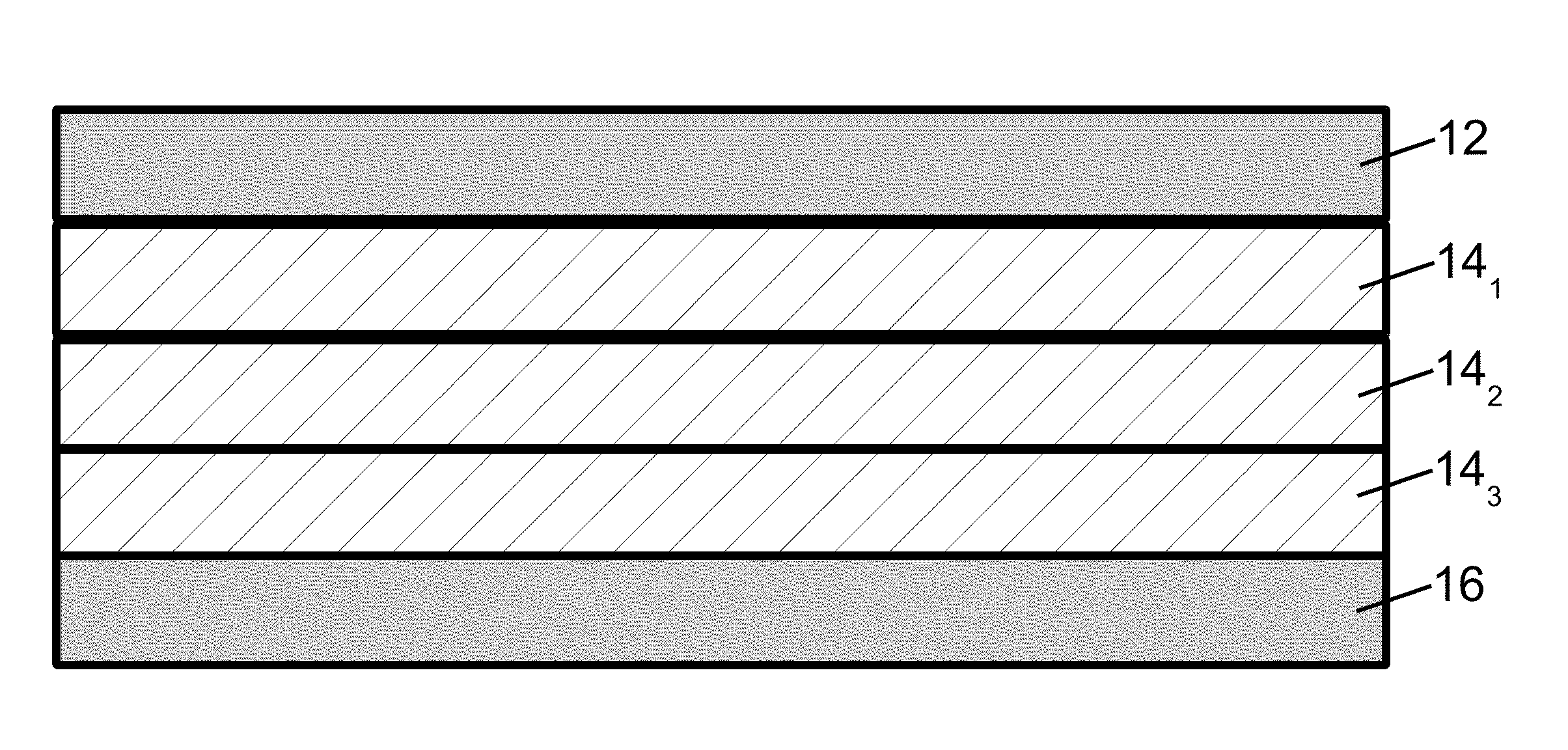
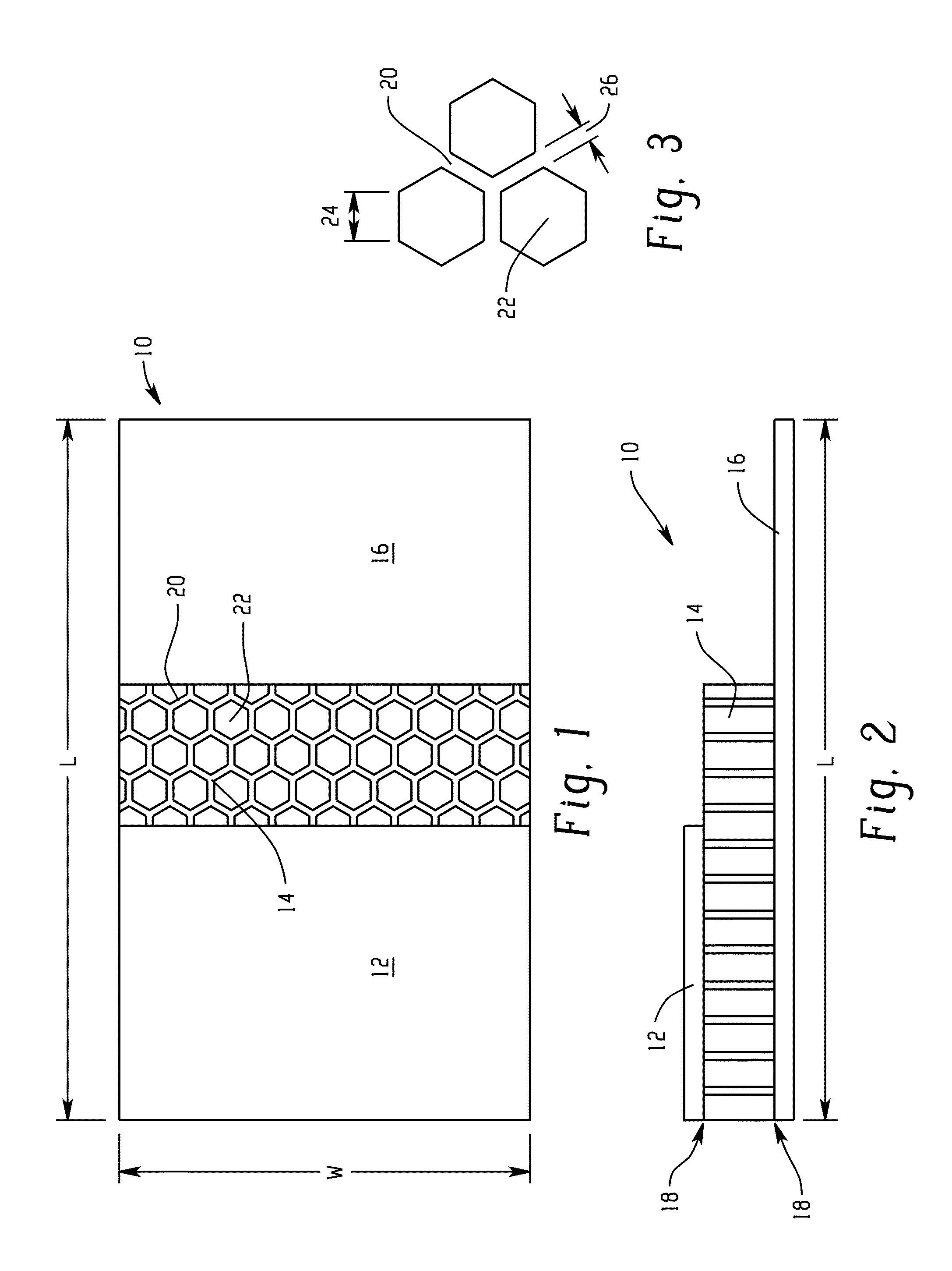
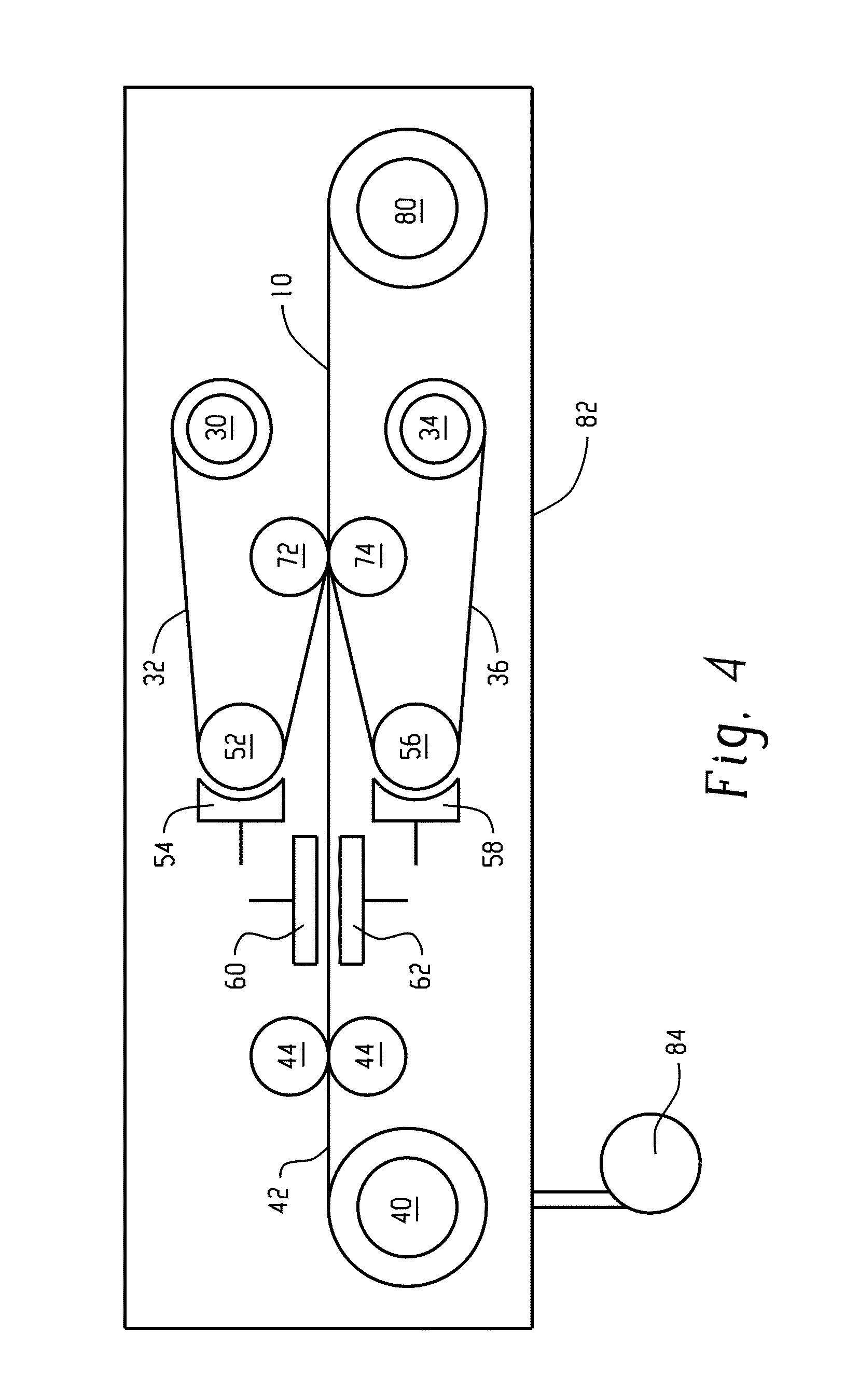
A stiff, lightweight metal laminate includes a first continuous metal layer, a second continuous metal layer, and a reduced density metal core layer disposed between the first and second continuous metal layers. The reduced density metal core layer comprises a core metal and has an average density that is less than the density of the core metal. Planar metallurgical bonds secure the first and second continuous metal layers to the reduced density metal core layer. The metal laminate may be manufactured by press rolling the reduced density metal core layer sandwiched between the two continuous metal layers, after removing or overcoating the native oxide layer on each layer surface that contacts another layer in the metal laminate.

Description

CROSS-REFERENCE TO RELATED APPLICATIONS[0001]This application claims priority to U.S. Provisional Patent Application Ser. No. 62 / 061,824, filed Oct. 9, 2014, and to U.S. Provisional Patent Application Ser. No. 62 / 181,436, filed Jun. 18, 2015. These applications are incorporated herein by reference in their entireties.BACKGROUND[0002]The present disclosure relates to stiff sheet materials usable to reduce the weight of stamped metal components, and particularly to a metal laminate sheet material.[0003]The need for lightweight materials is widespread across many industries. In the automotive and aerospace industries, lightweight materials are desired for improved fuel economy. In consumer recreational equipment, lightweight sheet material is desired for enhanced performance. In consumer electronics and mobile devices, using lightweight sheet material for device housings and other components enhances portability and provides a lighter device. More generally, manufacturers in such indus...

Claims


Application Information

Patent Timeline
IPC IPC(8): B32B15/01B23K20/04B21B1/22B32B3/30B32B3/26
CPCB32B15/016B32B15/012B32B15/011B32B2307/722B32B3/266B21B1/22B23K20/04B32B3/30B32B15/01B32B15/017
Inventor KAISER, JOSEPH G.VODNICK, AARON M.
Owner MATERION
Learn More