Methods and apparatus for heart failure treatment

a heart failure and treatment method technology, applied in the field of methods and apparatus for treating congestive heart failure, can solve the problems of reducing the capacity to circulate blood, the number of patients cannot account for the inability to reduce the number of patients, so as to achieve the effect of increasing the treatment pressure, increasing the treatment level, and increasing the pressur

Inactive Publication Date: 2007-06-14
UJHAZY ANTHONY JOHN +4
View PDF12 Cites 30 Cited by
  • Summary
  • Abstract
  • Description
  • Claims
  • Application Information

AI Technical Summary

Problems solved by technology

Of course, these numbers do not account for the number of patients in other countries who also suffer from heart failure.
Given these numbers, it is clear that congestive heart failure is a significant human crisis.
As the heart works less efficiently, its capacity to circulate blood decreases and the body's requirements for oxygen are not met.
This loss of contraction results in a decrease in the ability of the heart to force blood through the circulatory system of the body.
Left-sided heart failure occurs when the left ventricle does not sufficiently pump oxygenated blood to the body.
Right-sided heart failure occurs when the right ventricle does not pump adequately, which leads to fluid build-up in the veins.
This congestion is more commonly a symptom of systolic and left-sided heart failure.
At present, there are no known devices with features designed to treat a range of symptoms of heart failure patients through application of pressure as opposed to devices that might only incidentally provide such benefits.
However, the device is only taught to provide one continuous level of pressure during inspiration and another level during expiration.
Moreover, the device provides no assistance directed to alleviating Cheyne-Stokes breathing or distinguishing between obstructions due to vocal cord reflex and obstructions from typical OSA due to collapse of the upper airway during sleep.

Method used


Image

  • Methods and apparatus for heart failure treatment
  • Methods and apparatus for heart failure treatment
  • Methods and apparatus for heart failure treatment

Examples


Embodiment Construction

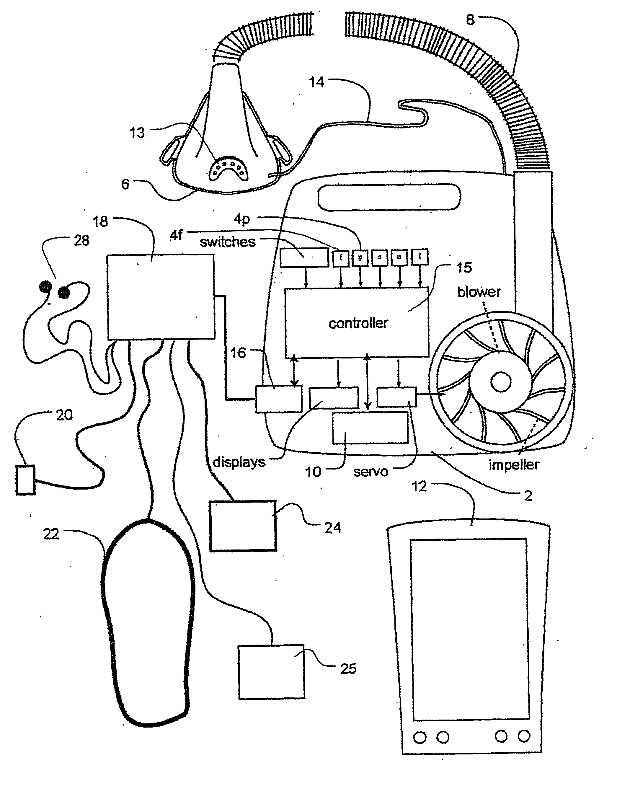
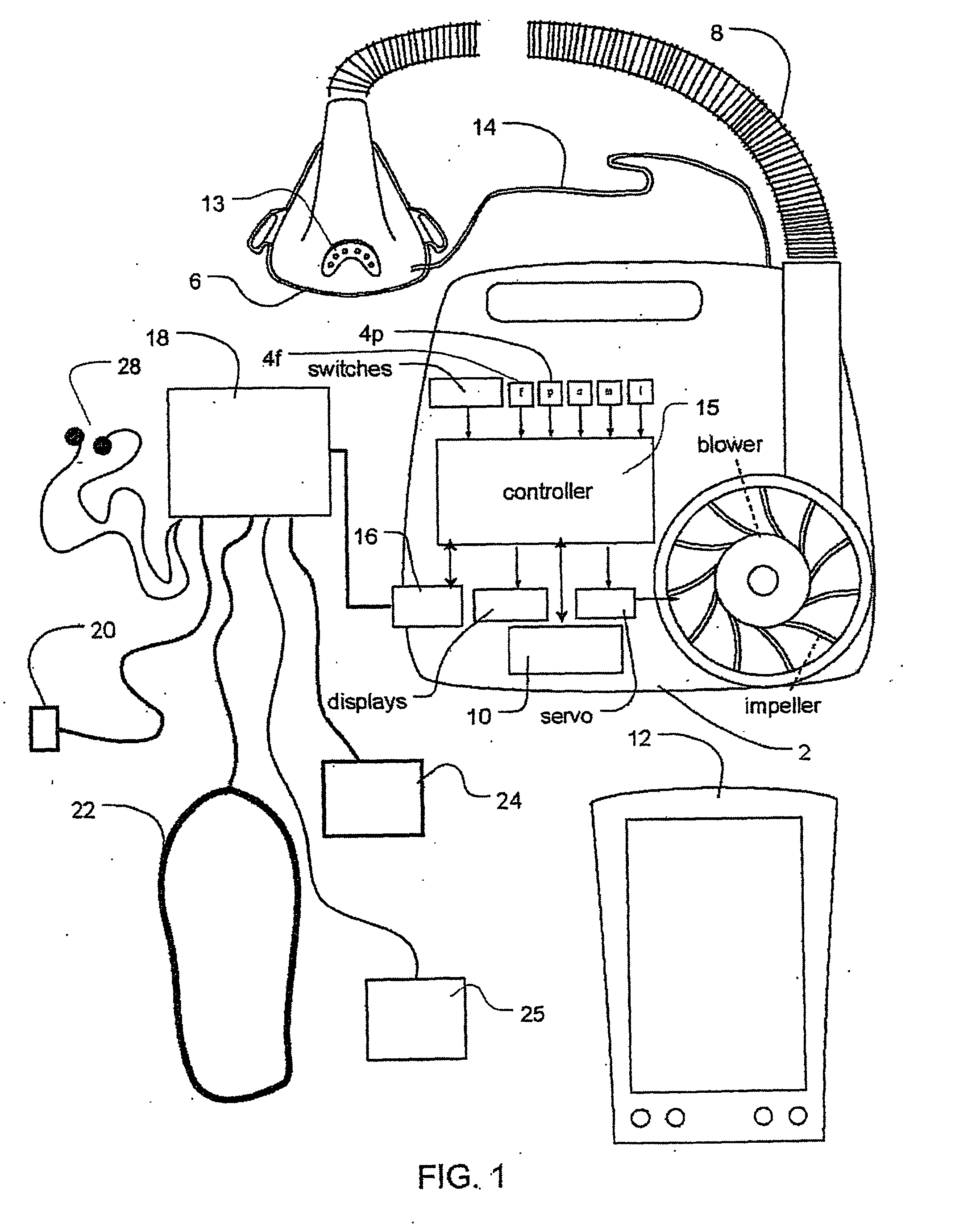
[0036] In reference to FIG. 1, the heart failure treatment invention involves an apparatus that includes a blower 2, a flow sensor 4f, pressure sensor 4p, a mask 6, and an air delivery conduit 8 for connection between the blower 2 and the mask 6. Exhaust gas is vented via exhaust 13. Mask flow is preferably measured using a pneumotachograph and differential pressure transducer to derive a flow signal F(t). Mask pressure is preferably measured at a pressure tap using a pressure transducer to derive a pressure signal Pmask(t). The pressure sensor 4f and flow sensor 4p have only been shown symbolically in FIG. 1 since it is understood that those skilled in the art would understand how to measure flow and pressure. Flow F(t) and pressure Pmask(t) signals are sent to a controller or microprocessor 15 to derive a pressure request signal PRequest(t). The controller or processor is configured to implement the methodology described in more detail herein and may include integrated chips, a me...


PUM


Abstract

Methods and apparatus for assessing the condition of and treating patients for heart failure by the delivery of continuous positive airway pressure are disclosed. Treatment of obstruction due to reflex vocal cord closure often experienced by heart failure patients is distinguished from treatment of upper airway obstruction typically associated with Obstructive Sleep Disorder. Treatment may also be implemented by delivering synchronized cardiac pressure oscillations superimposed on a respiratory pressure level to provide assistance for the heart. Heart treatment pressure dose indicator may be calculated for prescribing and monitoring the delivery of treatment. The apparatus may also generate data to track heart failure condition that may be indicative of the degree of severity of heart failure based upon breathing patterns to assist in the diagnosis and management of heart failure patients.

Description

FIELD OF THE INVENTION [0001] The invention relates to methods and apparatus for diagnosing, managing and treating congestive heart failure. BACKGROUND OF THE INVENTION [0002] It has been estimated that in the United States alone that almost five million people suffer from congestive heart failure. Statistics from the American Heart Association also suggest that new cases of heart failure are diagnosed at a rate of about 500,000 each year. Of the newly diagnosed patients fifty percent are likely to die within five years from the initial diagnosis. Of course, these numbers do not account for the number of patients in other countries who also suffer from heart failure. Given these numbers, it is clear that congestive heart failure is a significant human crisis. [0003] Heart failure is a condition that is characterized by a reduced ability of the heart to circulate blood through the body. Typically, an underlying disease, such as high blood pressure (e.g., hypertension), clogged arteri...

Claims


Application Information

Patent Timeline
Patent Type & Authority Applications(United States)
IPC IPC(8): A61B5/08A61M16/00
CPCA61M16/0051A61M2016/0021A61M2016/0036A61M2230/04A61M2230/10A61M2230/18A61M2230/435A61M2230/63A61M16/0066A61M16/06A61M16/0069A61B5/4836A61M16/024A61B5/0826A61B5/087A61B5/7282A61B5/746A61M16/0057A61M2205/3344A61M2230/005A61M2230/40
Inventor UJHAZY, ANTHONY JOHNWRIGHT, JONATHAN CADWELLRICHARDS, GLENNBASSIN, DAVID JOHNBERTHON-JONES, MICHAEL
Owner UJHAZY ANTHONY JOHN
Why Eureka
Try Eureka