
Catheter device

a catheter and catheter technology, applied in the field of catheter devices, can solve the problems of not being able to optimally integrate the conventional catheter into the medical workflow, putting a strain on the patient, entailing risks, etc., and achieve the effect of facilitating the inserting of the stent and being better integrated into the medical workflow

Inactive Publication Date: 2007-06-14
SIEMENS AG
View PDF26 Cites 204 Cited by
  • Summary
  • Abstract
  • Description
  • Claims
  • Application Information

AI Technical Summary

Benefits of technology

[0010] The problem underlying the invention is thus to provide a catheter device that is better integrated into the medical workflow and by means of which it can be made easier to insert a stent.

Problems solved by technology

That, though, is a procedure that puts a strain on the patient and entails risks, particularly in terms of restenosing.
Hitherto it has not been possible to optimally integrate the conventional catheters into the medical workflow.

Method used


Image

  • Catheter device
  • Catheter device
  • Catheter device

Examples


Embodiment Construction

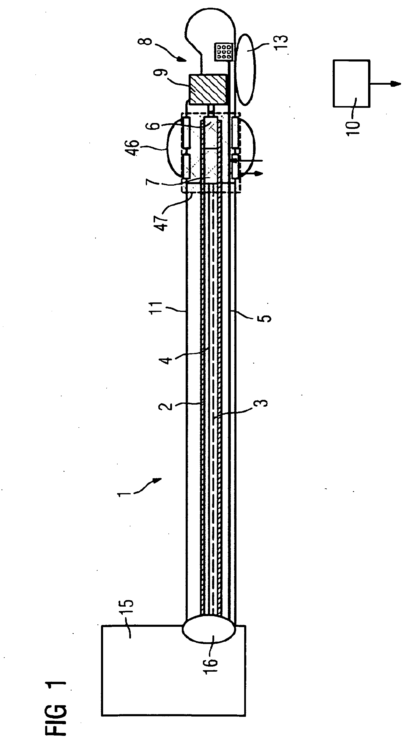
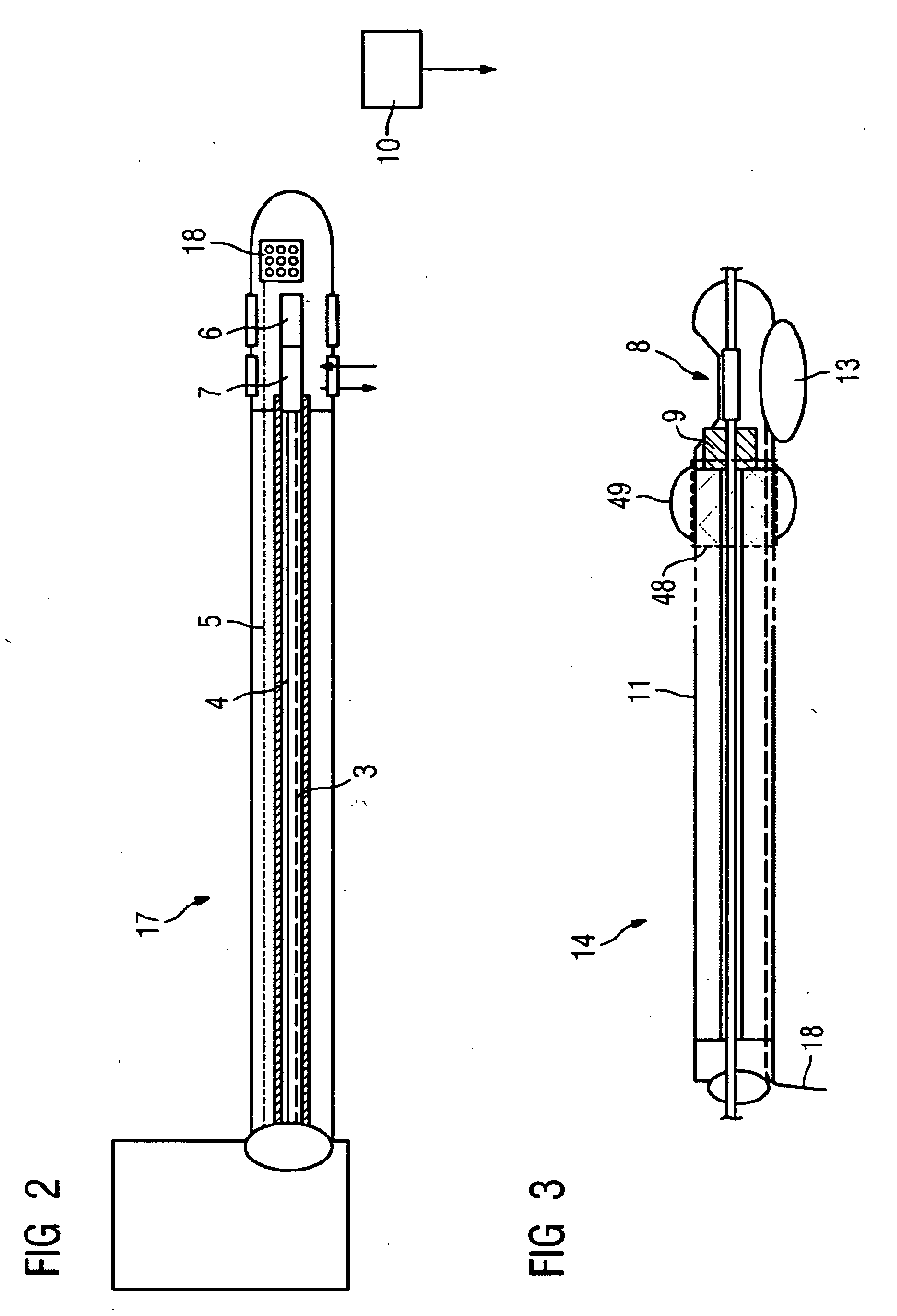
[0045]FIG. 1 shows an inventive catheter device 1 embodied as an atherectomy catheter. The inventive catheter device 1 has a hollow flexible drive shaft 2 in which an OCT signal lead 3 and an IVUS signal lead 4 are integrated. A signal lead 5 for a position sensor system embodied as an electromagnetic sensor system is furthermore arranged in the flexible drive shaft 2. An IVUS sensor 6 and an OCT sensor 7 are integrated in the front part of the catheter. An opening having a cutter 9 embodied as a rotating knife is located in the vicinity of the tip 8 of the catheter. A light-exit window for the OCT sensor 7 is located at the tip 8 of the catheter. Magnetic sensors of the sensor system are also located there. Said sensors interact with a position sensor 10 located outside the patient's body. The position sensor 10 is embodied as an electromagnetic sensor.

[0046] The catheter device moreover has a premounted stent 47 that is embodied as a metal-wire mesh and has here been sketched in ...


PUM


Abstract

The invention relates to a catheter device for performing an atherectomy, which device contains an atherectomy catheter and a stent premounted on the atherectomy catheter.

Description

CROSS REFERENCE TO RELATED APPLICATIONS [0001] This application claims priority of German application No. 10 2005 059 271.6 filed Dec. 12, 2005, which is incorporated by reference herein in its entirety. FIELD OF THE INVENTION [0002] The invention relates to a catheter device for performing an atherectomy. BACKGROUND OF THE INVENTION [0003] Vascular diseases are among the commonest disorders having a fatal outcome. Featuring most prominently is myocardial infarction due to diseased coronary vessels. When coronary vessels have become blocked by arteriosclerotic plaque, this clinical condition is customarily treated using percutaneous transluminal coronary angioplasty (PCTA) whereby the narrowed parts of the coronary vessels are dilated using a balloon catheter. However, clinical studies have shown that restenosing occurs in very many patients, with in some cases 50% of patients exhibiting this. An alternative method that has been known for a number of years is high-frequency rotablat...

Claims


Application Information

Patent Timeline
IPC IPC(8): A61F2/06A61F2/95
CPCA61B17/3207A61B19/5244A61B19/54A61B2017/00084A61B2017/22052A61B2019/2253A61B2019/5251A61B2019/547A61F2/95A61F2002/3067A61F2250/0002A61B34/20A61B34/73A61B90/39A61B2034/2051A61B2090/397
Inventor MASCHKE, MICHAEL
Owner SIEMENS AG
Learn More