Implant capable of forming a differential image in an eye and methods of inserting and locating same

Inactive Publication Date: 2007-06-14
HERRICK ROBERT S II
View PDF30 Cites 44 Cited by
  • Summary
  • Abstract
  • Description
  • Claims
  • Application Information

AI Technical Summary

Benefits of technology

[0053] Another advantage of the present invention is that the implant includes a collapsible expanded section which has an outer edge which is slideably urged against the interior walls of the punctum opening during insertion and placement within that portion of the canaliculus adjacent the punctum opening to hold the implant in position while concurrently occluding the canaliculus.
[0054] Another advantage of the present invention is that the canalicular implant is relatively easy to insert without the necessity of using an injectable anesthetic and can likewise be easily removed when located.
[0055] Another advantage of the present invention is that the permanent implant, when positioned in the punctum opening and that portion of the canaliculus adjacent the punctum opening, does not cause any tissue irritation or irritation to the eye due to migration of the same out of the canaliculus and through the punctum opening into the eye, but if the implant migrates, it can be located within the canliculus.
[0056] Another advantage of the present invention is that the punctum plug or implant using the teachings of the

Problems solved by technology

It is known in the art that certain eye problems are related to the volume of tears on the surface of the eyes.
The punctum plug of Freeman is subject to being inadvertently removed from the eye by the patient.
As the use of implants increases to treat the eye, several problems have been encountered.
Another know

Method used


Image

  • Implant capable of forming a differential image in an eye and methods of inserting and locating same
  • Implant capable of forming a differential image in an eye and methods of inserting and locating same
  • Implant capable of forming a differential image in an eye and methods of inserting and locating same

Examples


Example

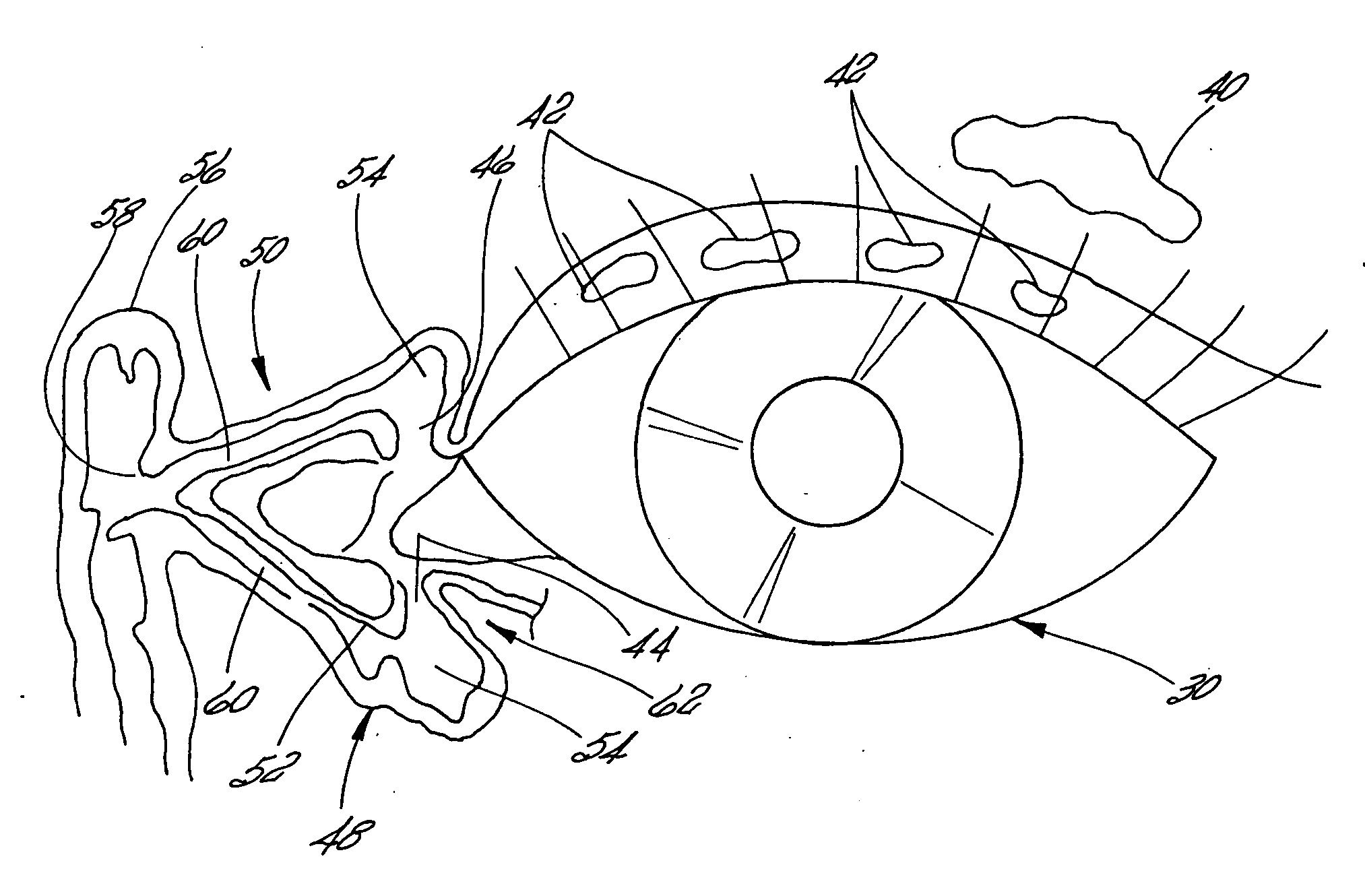
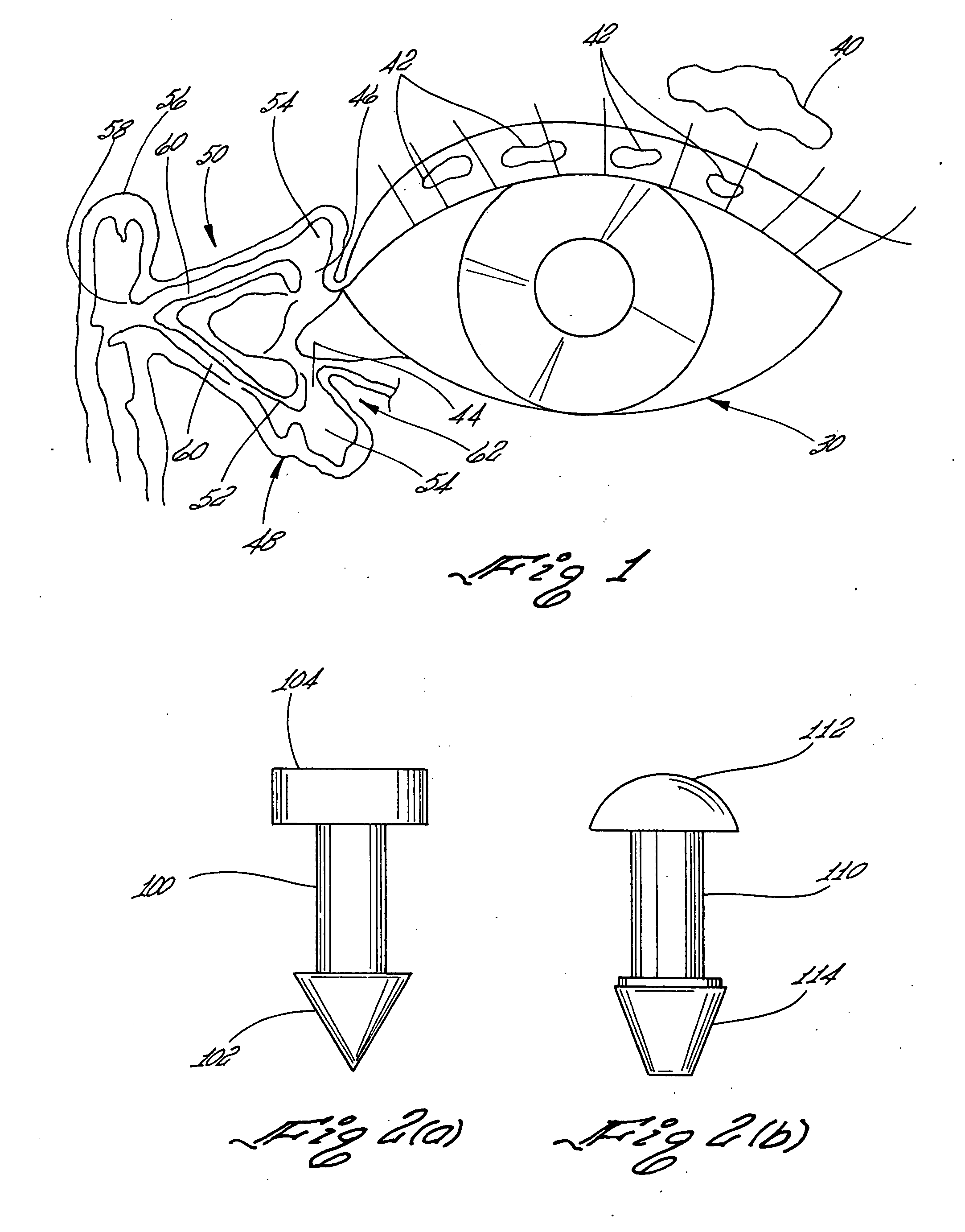
[0108] In order to better understand the teachings of the present invention, and the structure of the eye in its relationship to the present invention, the following brief description of the human eye and the associated lacrimal system illustrated in FIG. 1 and showing the paths of the tears from sources of the tears to the nasal cavity, will first be discussed.

[0109] The eye 30 includes a cornea and a pupil that is well known in the art. The source of the tears for the eye is generally classified into “crying tears” and “constant tears”. The “crying tears” are produced by a large lacrimal gland 40 illustrated in the upper right hand portion of the illustration of eye 30. The “constant tears” are produced by a series of small glands 42 which are located below the large gland 40 and spaced apart above the cornea of the eye 30. The “constant tears” are the tear secretions which are to be preserved in accordance with the teachings of the present invention.

[0110] In the normal eye, ap...


PUM


Abstract

An implant capable of forming a differential image in an eye is shown. The implant comprises an elongated member having a pair of spaced ends wherein one of the pair of ends includes a distal section that extends in a direction substantially parallel to the central axis. The elongated member and the distal section are formed of a dimension to be inserted into and/or passed through a punctum opening of an eye and into the canaliculus. The implant incorporates into at least one of the elongated member and the distal section an energy obstructing material responsive to the application of an energy wave, such as an energy wave in the form of sound waves vibrating at frequencies greater than 20,000 cycles per second or electromagnetic radiation, which upon everting of an eyelid of an eye and exposing the implant to an appropriate energy wave, forms a differential image pattern showing the location of the implant in the eye. Methods for treating an external eye condition due to a deficiency of tears and for locating an implant in the canaliculus of an eye using the implant capable of forming a differential image is also shown.

Description

CROSS-REFERENCES TO RELATED APPLICATIONS [0001] This Application claims the benefit, under Title 35, United States Code §119(e), of U.S. Provisional Patent Application Ser. No. 60 / 297,560 filed Jun. 11, 2001.STATEMENT REGARDING FEDERALLY SPONSORED RESEARCH OR DEVELOPMENT [0002] Not Applicable REFERENCE TO A “MICROFICHE APPENDIX” (SEE 37 CFR 1.96) [0003] Not Applicable BACKGROUND OF THE INVENTION [0004] 1. Field of the Invention [0005] The present invention relates to a an implant adapted to be utilized in the treatment of a human eye having a deficiency of tears and more specifically relates to an implant capable of forming a differential image in an eye wherein the implant includes an elongated member including a central axis and having at one end thereof a distal section which, in the preferred embodiment, is in the form of a collapsible expanded section. [0006] The distal section may terminate in a distal tip which extends in a direction substantially parallel to the central axis...

Claims


Application Information

Patent Timeline
IPC IPC(8): A61F2/14A61B17/00A61B17/12A61F9/007
CPCA61B17/12022A61B17/1204A61B17/12099A61B17/12159A61B2017/00004A61F9/00772
Inventor HERRICK, ROBERT S. II
Owner HERRICK ROBERT S II
Why Eureka
Try Eureka