Compact booster bleed turbofan

a turbofan, compact technology, applied in the direction of machines/engines, mechanical equipment, liquid fuel engines, etc., can solve the problems of increasing the size and weight of the fan frame, the typical booster bleed system is large and relatively complex, and the engine produces relatively low power

Inactive Publication Date: 2007-06-21
GENERAL ELECTRIC CO
View PDF12 Cites 37 Cited by
  • Summary
  • Abstract
  • Description
  • Claims
  • Application Information

AI Technical Summary

Problems solved by technology

However, at flight idle operation during landing approach of the aircraft the engine produces relatively low power, and the HPC requires correspondingly less airflow therethrough.
The typical booster bleed system is relatively large and relatively complex and is located between the booster and high pressure compressors.
Any hole or aperture placed in the structural hub of the fan frame interrupts the structural integrity thereof and correspondingly requires strengthening of the hub which typically increases size and weight of the fan frame.
The bleed system mounted inside the typical fan frame of a large turbofan engine increases the cost of manufacture of the engine, increases weight of the engine, and correspondingly decreases overall efficiency of the engine.
In one engine undergoing development, the fan frame includes a relatively small center hub which lacks available space for introducing a conventional booster bleed system.
Furthermore, components adjoining the fan frame have limited available space for mounting those components themselves, without the additional complication of introducing a suitable booster bleed system.

Method used


Image

  • Compact booster bleed turbofan
  • Compact booster bleed turbofan
  • Compact booster bleed turbofan

Examples


Embodiment Construction

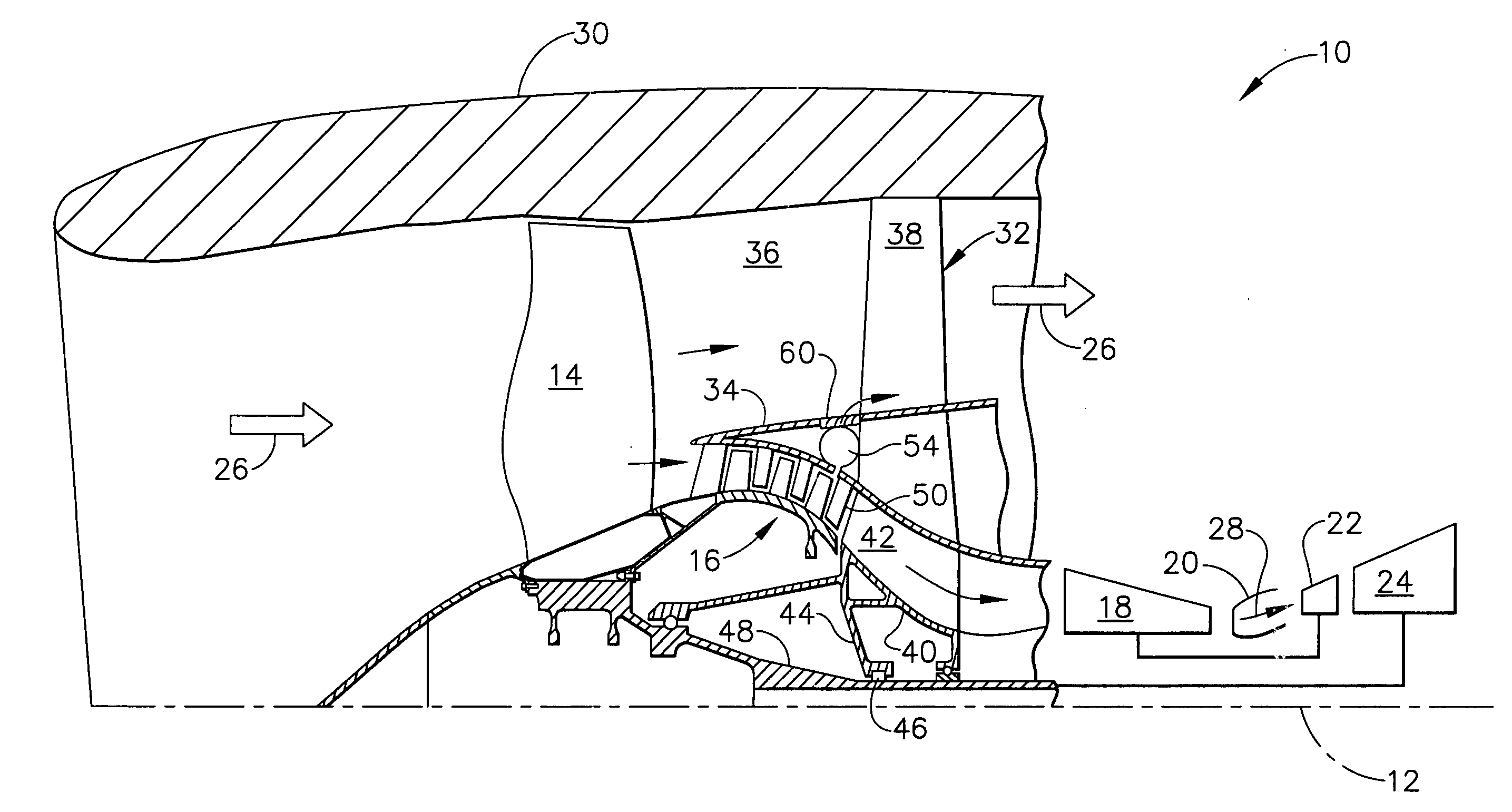
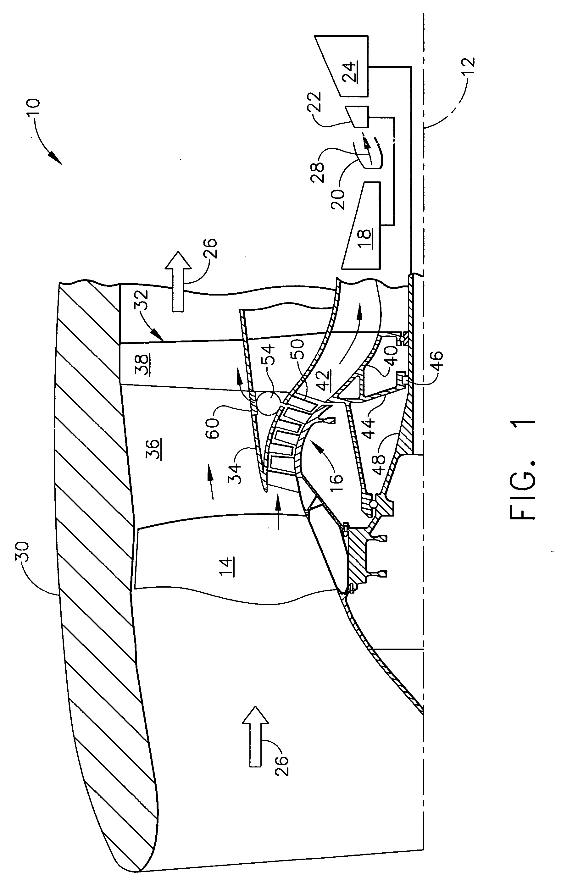
[0023] Illustrated schematically in FIG. 1 is a turbofan aircraft gas turbine engine 10 configured for powering an aircraft (not shown) in flight from takeoff to cruise to landing in the typical cycle of operation over the flight envelope. The engine is axisymmetrical about a longitudinal or axial centerline axis 12, and suitably mounted to the wing or fuselage of the aircraft.

[0024] The engine includes in serial flow communication a fan 14, booster or low pressure compressor 16, high pressure compressor 18, combustor 20, high pressure turbine (HPT) 22, and low pressure turbine (LPT) 24. The HPT or first turbine 22 is joined by one drive shaft to the high pressure or second compressor 18. And, the LPT or second turbine 24 is joined by another drive shaft to both the fan 14 and booster or first compressor 16.

[0025] In typical operation, air 26 is pressurized by the fan 14 and an inner portion of this air is channeled through the first compressor 16 which further pressurizes the air...


PUM


Abstract

A Turbofan engine includes a fan mounted to a fan frame inside a fan nacelle. A booster compressor is joined to the fan inboard a flow splitter. A booster bleed system is disposed inside the splitter, and includes an inlet at the compressor outlet, and an outlet joined to the bypass duct following the fan

Description

BACKGROUND OF THE INVENTION [0001] The present invention relates generally to gas turbine engines, and, more specifically, to bleed systems therein. [0002] A turbofan aircraft engine includes a fan mounted inside a surrounding nacelle, and is driven by a low pressure turbine (LPT). An inner portion of air channeled through the fan enters a core engine in which the air is pressurized in a high pressure compressor (HPC) and mixed with fuel in a combustor for generating hot combustion gases. Energy is extracted from the combustion gases in a high pressure turbine (HPT) that drives the compressor. [0003] The outer portion of fan air bypasses the core engine through an annular bypass duct. The pressurized air discharged from the bypass duct provides a majority of propulsion thrust of the engine for powering an aircraft in flight. [0004] In large turbofan engines, additional power is generated by including a low pressure or booster compressor behind the fan and in front of the HPC of the ...

Claims


Application Information

Patent Timeline
Patent Type & Authority Applications(United States)
IPC IPC(8): F02C6/08
CPCF01D17/105F02C9/18F02K3/075Y02T50/671F05D2270/101F04D27/0215F04D27/023F04D29/522Y02T50/60
Inventor MONIZ, THOMAS ORY
Owner GENERAL ELECTRIC CO
Why Eureka
Try Eureka