Structure and method for improving flow uniformity and reducing turbulence

a technology of flow uniformity and flow velocity, applied in the field of fluid flow non-uniformity and turbulence control, can solve the problems of reducing flow uniformity, reducing flow uniformity, and reducing lateral turbulence, so as to reduce flow acoustics, reduce flow turbulence, and reduce lateral turbulen

Inactive Publication Date: 2007-06-21
VAKILI AHMAD D
View PDF10 Cites 11 Cited by
  • Summary
  • Abstract
  • Description
  • Claims
  • Application Information

AI Technical Summary

Benefits of technology

[0009] An application of the present invention is directed toward a structure for establishing a uniformly flowing fluid. The structure includes a wind tunnel wherein the flowing fluid is contained within the wind tunnel. In an alternative embodiment, the wind tunnel is a nacelle of an engine. A propulsion means is positioned inside of the wind tunnel for accelerating the fluid through the wind tunnel. A target area having an inlet for receiving the flowing fluid is located in the wind tunnel wherein a uniform fluid flow is desired in the target area. The target area may be an area wherein it is desired to modify sound waves in the fluid. Flow generated sound waves are caused by the flow turbulence and, therefore, reduction of flow acoustics can be accomplished as well by reductions in flow turbulence. A turbulence filter is positioned in the wind tunnel upstream of the target area. The turbulence filter includes a plurality of substantially parallel channels having a fluid inlet, a fluid outlet, and sidewalls for reducing lateral turbulence in the fluid flow. The substantially parallel channels preferably have a hexagonal cross section. A plurality of openings in the sidewalls of a portion of each of the plurality of channels allows lateral fluid communication between the channels. In a most preferred embodiment, the openings are only on a portion of the channel sidewalls that is adjacent to the fluid inlet. The openings are dimensioned to provide a degree of lateral communication between the fluid flowing in adjacent channels to reduce non-uniformity and turbulence.
[0010] Yet another embodiment of the present invention is directed toward an apparatus for establishing a uniform fluid flow in a fluid channel. The apparatus includes a wind tunnel or fluid channel that has a propulsion means positioned therein for creating a fluid flow inside of the wind tunnel. A target chamber is positioned inside of the wind tunnel wherein a uniform, low turbulence fluid flow is desired. In a most preferred embodiment, an aircraft model is positioned in the target area. A stilling chamber is positioned upstream of the target chamber inside of the wind tunnel. A conduit bundle is positioned in the stilling chamber for reducing turbulence in the fluid flow. The conduit bundle includes a plurality of longitudinal channels that receive the fluid flow from the propulsion means wherein each longitudinal channel has a plurality of transverse perforations that allow for fluid flow through adjacent conduits. Preferably, the channels have approximately equal cross sectional areas. The transverse perforations are dimensioned to allow sufficient lateral fluid communication between the channels to substantially equalize the fluid pressure in each channel. The density of the transverse perforations per unit length of conduit varies for at least some of the conduits.

Problems solved by technology

Generally speaking, any structure placed in a fluid will cause some turbulence when the fluid begins to flow.
In addition, as the speed of a flowing fluid increases, the effects of the turbulence become more pronounced.
The viscous wake is convectively unstable and rolls into large-scale coherent rotational flow regions.
These vortices develop higher frequency instabilities and eventually decay into turbulence.
For large wind tunnels, there are at least two problems associated with this methodology.
The first problem is that a wire screen extended over a large span does not retain its intended planar shape.
The flow downstream of the deformed screen is, therefore, non-uniform and produces flow angularity in the test section.
The second problem is the large required size of the stilling chamber necessary to produce the contraction ratio that is essential to reducing flow stream turbulence close to the desired value.
On the basis of both cost and mechanical considerations, the stilling chamber size requirement is especially limiting for the design of high Reynolds' number facilities which are often pressurized.
However, the wire diameter must be increased to reduce deformation due to increased loads on the screen and in turn, increases the turbulence level in the test section and requires a longer, and more expensive, contraction section to provide for increased decay of turbulence exiting the screen.
Unfortunately, the smoothness of the walls does not help reduce turbulence in the center of the fluid flow and the screens tend to bend and produce turbulent vortices at higher flow velocities.
However, there are currently no methods for reducing the internal turbulence in the flowing fuel and air mixture itself.
This variability in flow uniformity reduces the engines' overall performance and efficiency.

Method used


Image

  • Structure and method for improving flow uniformity and reducing turbulence
  • Structure and method for improving flow uniformity and reducing turbulence
  • Structure and method for improving flow uniformity and reducing turbulence

Examples


Embodiment Construction

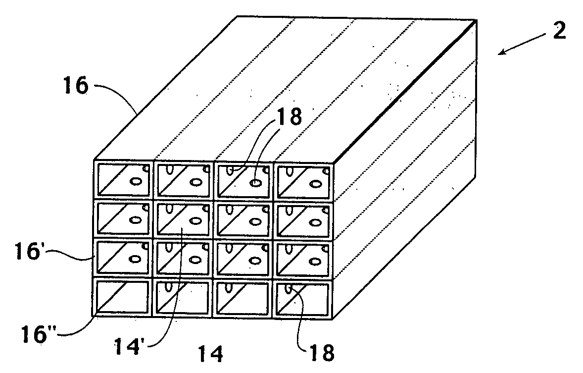
[0021] In accordance with the aforementioned deficiencies in the prior art, a new structure has been designed and developed by the present inventor for alleviating the design dilemma between screen deformation and induced vorticity such that high quality fluid flows can be established. In addition, the present invention is well suited to efficient and cost-effective manufacture. Therefore, the present invention provides new possibilities not previously available to wind tunnel designers, as well as designers other various applications.

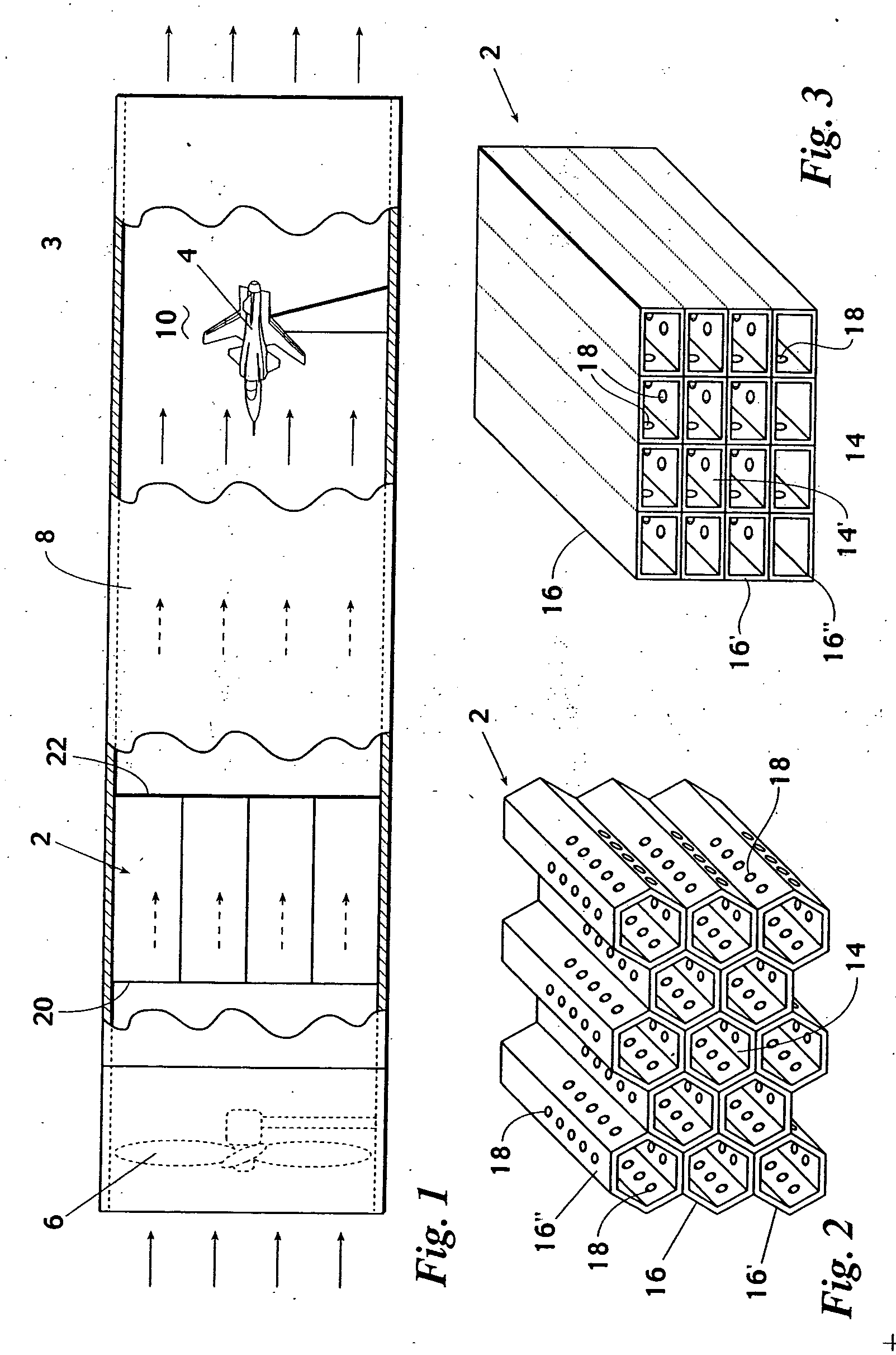
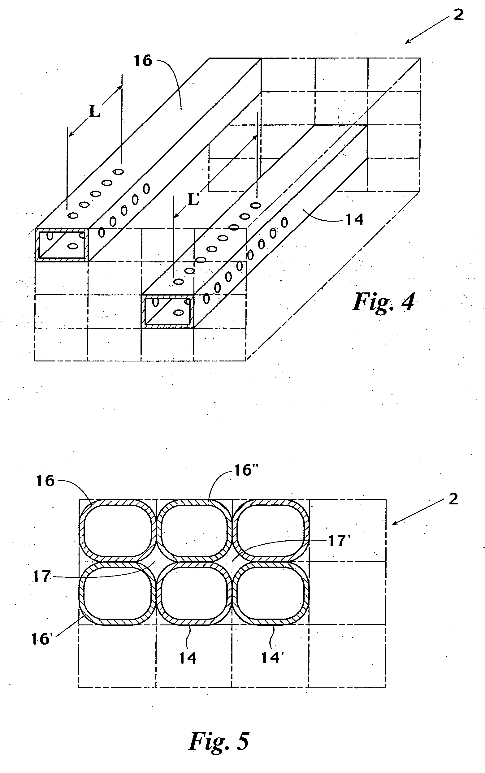
[0022] Referring now to FIG. 1, a preferred embodiment of the present invention in the form of a conduit bundle 2 for use in the stilling chamber of a wind tunnel 3 is shown. The conduit bundle 2 eliminates the need for a screen in the stilling chamber of the wind tunnel 3. The wind tunnel 3 would typically be used for testing the aerodynamic properties of a test subject 4 such as a jet. The wind tunnel 3 has an apparatus such as a fan 6 for passing a...


PUM


Abstract

A structure for reducing turbulence and increasing flow uniformity in a flowing fluid in a wind tunnel, or a fluid channel, has a plurality of conduits or channels arranged into a conduit bundle. The conduit bundle has a number of parallel conduits with plurality of perforations on the inner side walls of the conduit. As the fluid flows through the conduit bundle the sides of the conduits reduce lateral turbulence while the perforations minimize pressure gradients in the flowing fluid in adjacent conduits, resulting in isotropic turbulence. The invention is particularly useful in testing aircraft, improving engine performance, and fluid mechanics applications.

Description

CROSS REFERENCES TO RELATED APPLICATIONS [0001] The present application is a continuation-in-part of, and claims priority from, application Ser. No. 10 / 084,164, filed on Feb. 28, 2002, which claimed priority from provisional application Ser. No. 60 / 271,613, filed on Feb. 26, 2001.FIELD OF THE INVENTION [0002] The invention disclosed herein broadly relates to the field of fluid flow non-uniformity and turbulence control. More particularly, the present invention relates to the use of a honeycomb structured conduit bundle for altering fluid flow non-uniformity to produce highly uniform flows with low turbulence and acoustic attenuation that is particularly useful for managing flow in a wind tunnel. BACKGROUND OF THE INVENTION [0003] When dealing with flowing fluids, it is often desirable to reduce the non-uniformity and turbulence in the flowing fluid. Generally speaking, any structure placed in a fluid will cause some turbulence when the fluid begins to flow. In addition, as the speed...

Claims


Application Information

Patent Timeline
Patent Type & Authority Applications(United States)
IPC IPC(8): F15D1/04F15D1/02G01M9/04
CPCF15D1/02G01M9/04
Inventor VAKILI, AHMAD D.
Owner VAKILI AHMAD D
Why Eureka
Try Eureka