Method of manufacturing heat exchanger tube and heat exchanger

Inactive Publication Date: 2007-06-21
DENSO CORP +1
View PDF2 Cites 39 Cited by
  • Summary
  • Abstract
  • Description
  • Claims
  • Application Information

AI Technical Summary

Benefits of technology

[0009]In recent years, friction stir welding (FSW) has been developed and expected to be applied in various fields. Therefore, a number of welding methods have been proposed. FSW is one type of solid-state welding method in which a hard tool is inserted into a soft metal such as aluminum while being rotated to produce a plastic flow due to frictional heat, followed by stirring to effect welding. The inventors have attempted to seal the above portion by FSW. As a result, the inventors have found that a portion with a thickness of about 2 mm or more is necessary in order to obtain a strong junction without causing the matrix to be buckled, and it is difficult to obtain a strong junction with a large junction depth for a portion with a small thickness.
[0010]On the other hand, the inventors have found that it suffices that these portions be welded to such an extent that these portions can withstand handling before brazing and thermal strain during brazing and a filler metal does not enter during brazing, and that a joint having such properties can be obtained even if the junction depth is s

Problems solved by technology

However, it is difficult to control welding so that an appropriate joint is formed in such a thin portion.
Moreover, a complicated instrument is required.
As a result, the inventors have found that a portion with a thickness of

Method used


Image

  • Method of manufacturing heat exchanger tube and heat exchanger
  • Method of manufacturing heat exchanger tube and heat exchanger
  • Method of manufacturing heat exchanger tube and heat exchanger

Examples


example 1

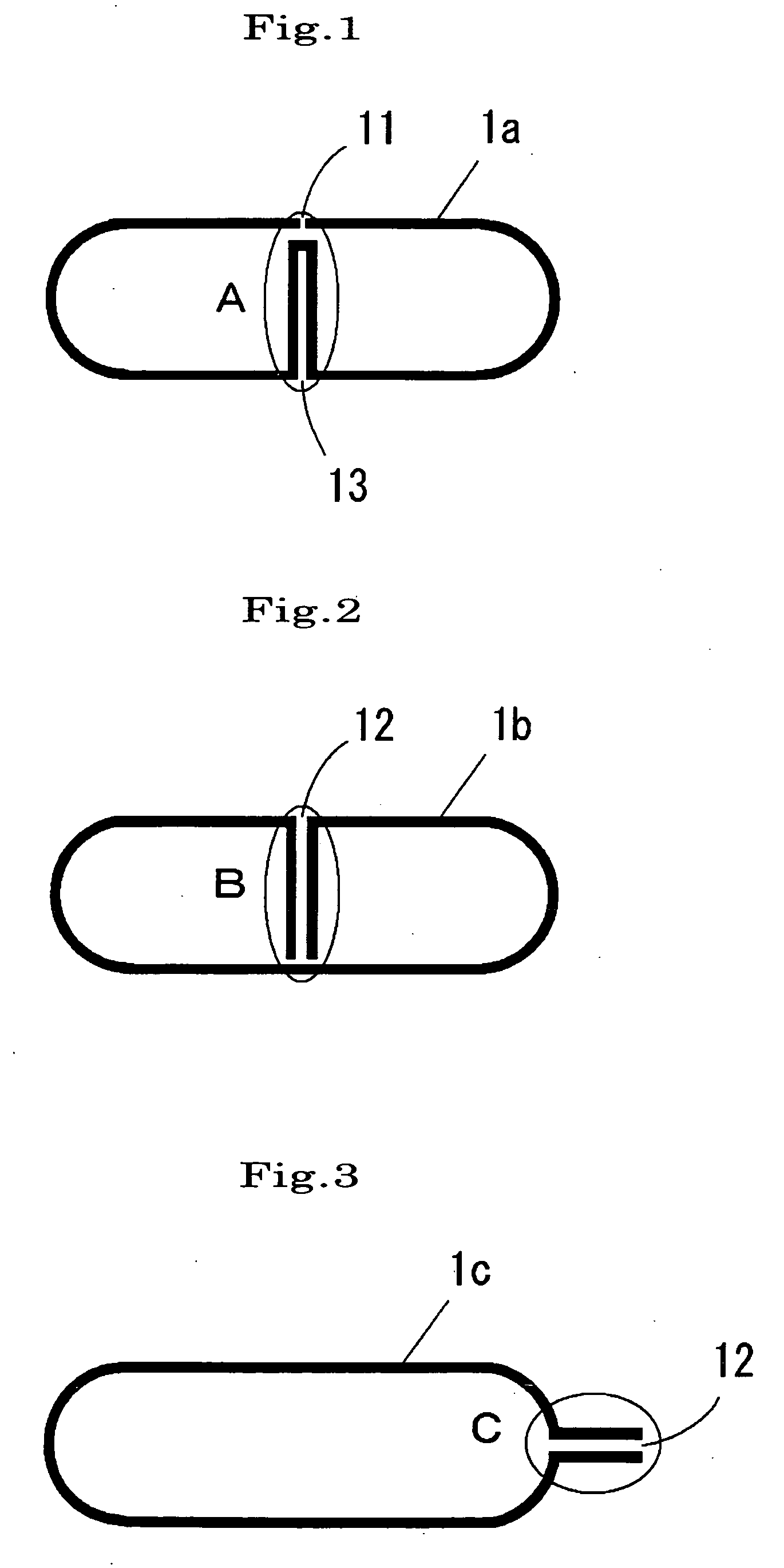
[0055]An Al—Mn aluminum alloy sheet (thickness: 0.2 mm) in which a sacrificial anode material Al—Zn alloy was clad on its outer surface was bent into a flat tube shape as shown in FIG. 3, and a parallel portion of the end portions was formed. An inner fin (thickness: 0.1 mm) formed of a corrugated Al—Mn aluminum alloy (Al—Si alloy filler metal was clad on both sides) was inserted into the flat tube. The end portion of the inner fin was placed between the aluminum alloy sheet portions forming the parallel portion to form an end portion in which the three portions were stacked.

[0056]The parallel portion and the end portion in which the three portions were stacked were restrained using steel plates with a thickness of 5 mm. A cylindrical steel rotating tool with a diameter of 0.5 mm was pressed against the side surfaces of the parallel portion and the end portion while rotating the tool at a rotational speed of 1500 rpm. The tool was moved in the longitudinal direction (width direction...

example 2

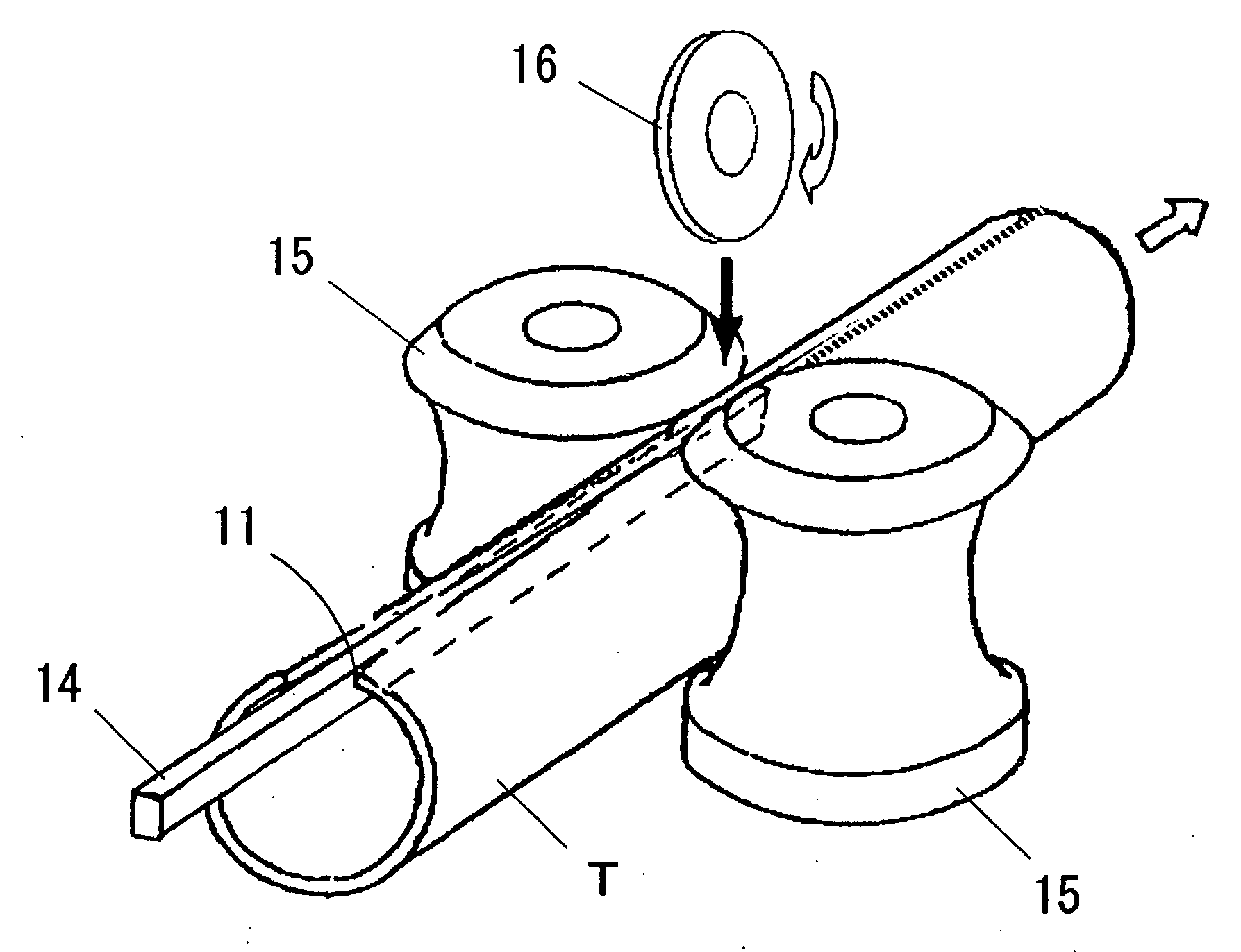
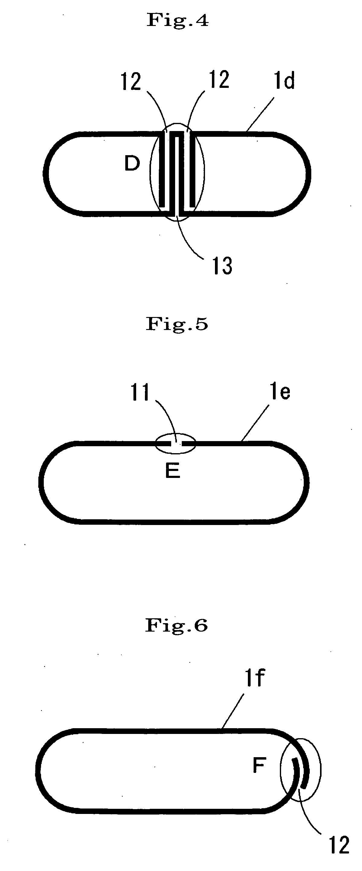
[0058]An Al—Mn aluminum alloy sheet (thickness: 0.2 mm) in which a sacrificial anode material Al—Zn alloy was clad on its outer surface was bent into a flat tube shape as shown in FIG. 5, and an opposing portion of the end portions was formed.

[0059]As shown in FIG. 19, the opposing portion was restrained using a steel backing jig and forming rollers. A disk-shaped steel roller with a diameter of 200 mm and a width of 0.5 mm was pressed against the opposing portion while rotating the roller at a rotational speed of 3000 rpm. The opposing portion was moved at a speed of 100 m / min to cause frictional heat generation to occur due to sliding, thereby welding the opening in the opposing portion.

[0060]The resulting tube was inserted into a header tube, and subjected to Nocolok brazing (brazing using fluoride flux) in which the tube was heated at a temperature of about 600° C. for three minutes. As a result, the filler metal did not enter the joint during brazing, and the amount of filler m...


PUM

PropertyMeasurementUnit
Shapeaaaaaaaaaa

Abstract

The present invention provides a method of manufacturing a heat exchanger tube in which a tube for a heat exchanger formed by brazing is manufactured using a sheet material, wherein a filler metal melted during brazing can be prevented from entering an opening formed in an opposing portion or a parallel portion formed when bending a sheet material into a tube shape or an opening facing toward the outside of the tube. The opposing portion, the parallel portion, or the opening facing toward the outside of the tube is sealed. As the sealing means, friction welding is preferable.

Description

BACKGROUND OF THE INVENTION[0001]1. Field of the Invention[0002]The present invention relates to a method of manufacturing a heat exchanger tube in which a tube for a heat exchanger formed by brazing is manufactured using a sheet material, and a heat exchanger in which a tube obtained by the manufacturing method is incorporated and integrated by brazing.[0003]2. Description of Related Art[0004]An extruded flat multi-channel tube has been used as a tube for automotive aluminum heat exchangers. In order to reduce the weight of heat exchangers, tubes obtained by forming a sheet material have been proposed. Examples of such tubes include tubes 1a and 1e shown in FIGS. 1 and 5 formed by bending an aluminum sheet material into a tube shape so that the end portions are oppositely positioned, tubes 1b, 1c, and 1f shown in FIGS. 2, 3, and 6 in which the end portions are disposed in parallel, a tube 1d shown in FIG. 4 in which the end portion and a portion other than the end portion are dispo...

Claims


Application Information

Patent Timeline
IPC IPC(8): B23K20/12
CPCB21C37/0803B21C37/151B23K1/0012B23K20/12B23K2201/14F28D1/0391F28F21/084F28F21/085B23K2101/14
Inventor NISHIKAWA, HIROSHIGOTYO, KENTAHATTORI, TAKASHIKUMAGAI, MASAKIITOH, YASUNAGA
Owner DENSO CORP
Why Eureka
Try Eureka