Motor attached with torque transmission member
a technology of torque transmission and torque, which is applied in the direction of magnetic circuit rotating parts, magnetic circuit shapes/forms/construction, instruments, etc., can solve the problems of gear engagement, shift around, and the rotation stopping mechanism is not arranged on the gear, so as to prevent the influence of the torque transmission member
- Summary
- Abstract
- Description
- Claims
- Application Information
AI Technical Summary
Benefits of technology
Problems solved by technology
Method used
Image
Examples
second example
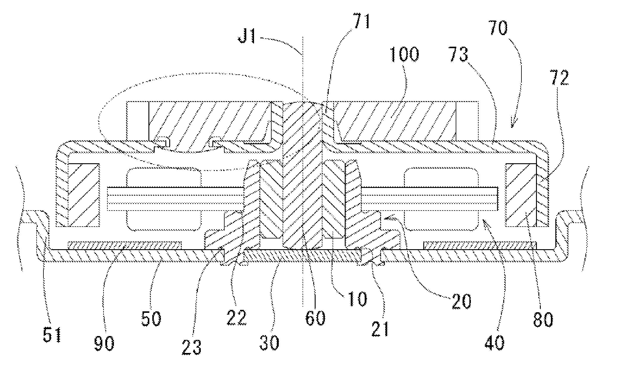
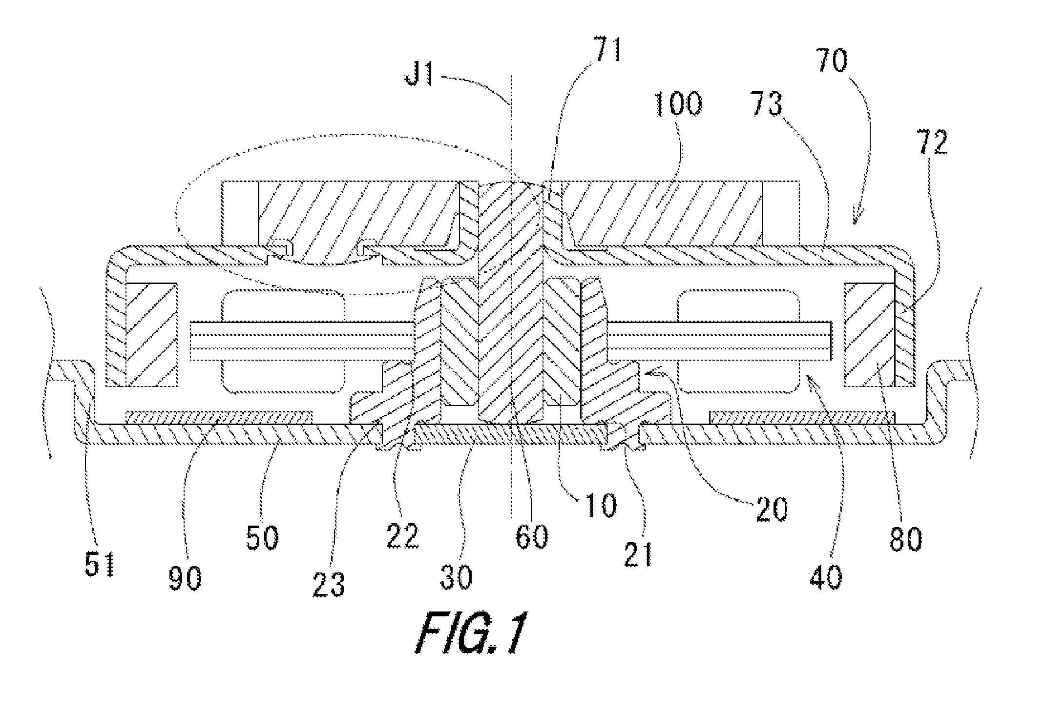
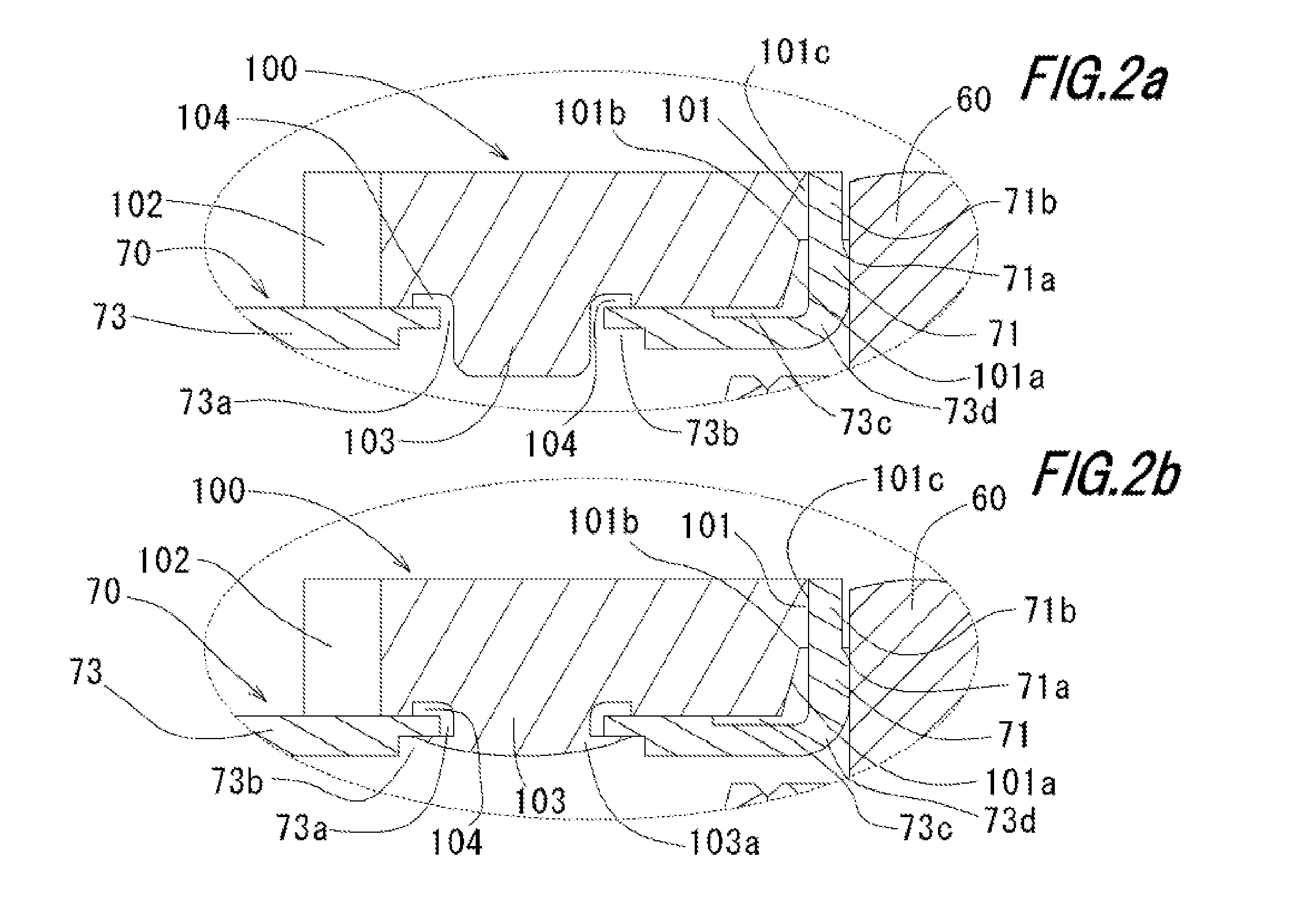
[0048] The second example of the attachment configuration of the gear 100 according to the present invention will now be described using FIGS. 3 to 5. The shapes of the rotor holder and the gear are slightly deformed, and thus will be respectively described as rotor holder 110 and gear 120. FIG. 3 is a view of the same position as the enlarged view of the dotted circle of FIG. 1, FIG. 4a) is a view seen from the lower side of the rotor holder 110, FIG. 4b) is a cross sectional view taken along line A-A, and FIG. 4c) is a cross sectional view taken along line B-B. FIG. 5 is a perspective view of a fitting member 130. The alignment mechanism of the gear 120 is the same as the above example, and thus the description thereof will be omitted. The configuration of attaching the gear 120 to the plate-like portion 113 of the rotor holder 110 will be described herein.
[0049] With reference to FIG. 3, a plate-like portion pass through hole 113a is formed at the plate-like portion 113 of the r...
third example
[0054] The third example of the present invention will now be described using FIG. 6. FIG. 6 is an enlarged view of the same position as the dotted circle of FIG. 1. The shape of the rotor holder is slightly deformed, and thus will be described as rotor holder 140 below. The gear has the same shape as in the second example, and thus will be described as gear 120.
[0055] A plate-like portion projection 143a projecting toward the upper surface of the plate-like portion 143 is formed at the plate-like portion 143 of the rotor holder 140. The plate-like portion projection 143a may be half die cutting processed. Alternatively, it may be burling processed. The plate-like portion projection 143a is fixed with the gear side concave part 121 of the gear 120 through press fit or adhesion. If the fixing method is adhesion, a predetermined cavity 143b is formed between the corner of the plate-like portion projection 143a and the corner of the gear side concave part 121 facing the corner, so tha...
fourth example
[0056] A fourth example of the present invention will now be described using FIG. 7. FIG. 7 is an enlarged view of the same position as the dotted circle of FIG. 1. The shapes of the rotor holder and the gear are slightly deformed, and thus will be described as rotor holder 150 and gear 160 below.
[0057] A plate-like portion projection 153a of a cylindrical shape projecting toward the upper surface of the plate-like portion 153 is formed at the plate-like portion 153 of the rotor holder 150. A gear side concave part 161 is formed in the lower surface of the gear 160. A lower surface projection 162 projecting toward the lower side is formed at the central part of the gear side concave part 161. The lower surface projection 162 is inserted into and fixed to the plate-like portion projection 153a. The fixation of the lower surface projection 162 and the plate-like portion projection 153a may be through press fit, adhesion, thermal deformation and the like.
PUM
 Abstract
Description
Claims
Application Information
 - R&D
- Intellectual Property
- Life Sciences
- Materials
- Tech Scout
- Unparalleled Data Quality
- Higher Quality Content
- 60% Fewer Hallucinations
Browse by: Latest US Patents, China's latest patents, Technical Efficacy Thesaurus, Application Domain, Technology Topic, Popular Technical Reports.
© 2025 PatSnap. All rights reserved.Legal|Privacy policy|Modern Slavery Act Transparency Statement|Sitemap|About US| Contact US: help@patsnap.com


