
Adaptor Assembly

Active Publication Date: 2013-06-20
RADIUS SYST LTD
View PDF5 Cites 4 Cited by
  • Summary
  • Abstract
  • Description
  • Claims
  • Application Information

AI Technical Summary

Benefits of technology

The patent text describes a device that is used in electrical equipment to prevent electrical arcing. The device includes a compression element and a piston, which can move relative to each other. To prevent torque from being transmitted between the two parts, a first slip spacer is used. This spacer allows the transmission of axial load from the compression element to the piston, but substantially prevents the transmission of torque. This prevents damage to the insulation coating on the piston and helps to keep the piston and the compression element spatially separated, reducing the risk of electrical arcing.

Problems solved by technology

However, it is found that the introduction of a lining pipe having a smaller diameter than the host pipe, leads to an inevitable increase in head loss.
Therefore, the longer and narrower a pipe is, the greater the head loss will be.
The length of the 16 mm PE pipe is generally not limited and so the head loss incurred in these installations is often excessive.
The potential for excessive head losses has led to the prohibition of such practice in some areas, leaving expensive open cut techniques as alternatives.
Other problems are associated with providing an effective and adequate joint from the new plastic service pipe to a fitting, such as a valve or meter, for example.
In practice, the use of an additional piece of apparatus for electrical isolation is inconvenient (and in many cases impractical), whilst adding to the complexity of connecting a service pipe to a domestic pipe system and increasing the number of potential leak paths.

Method used


Image

  • Adaptor Assembly
  • Adaptor Assembly
  • Adaptor Assembly

Examples


Embodiment Construction

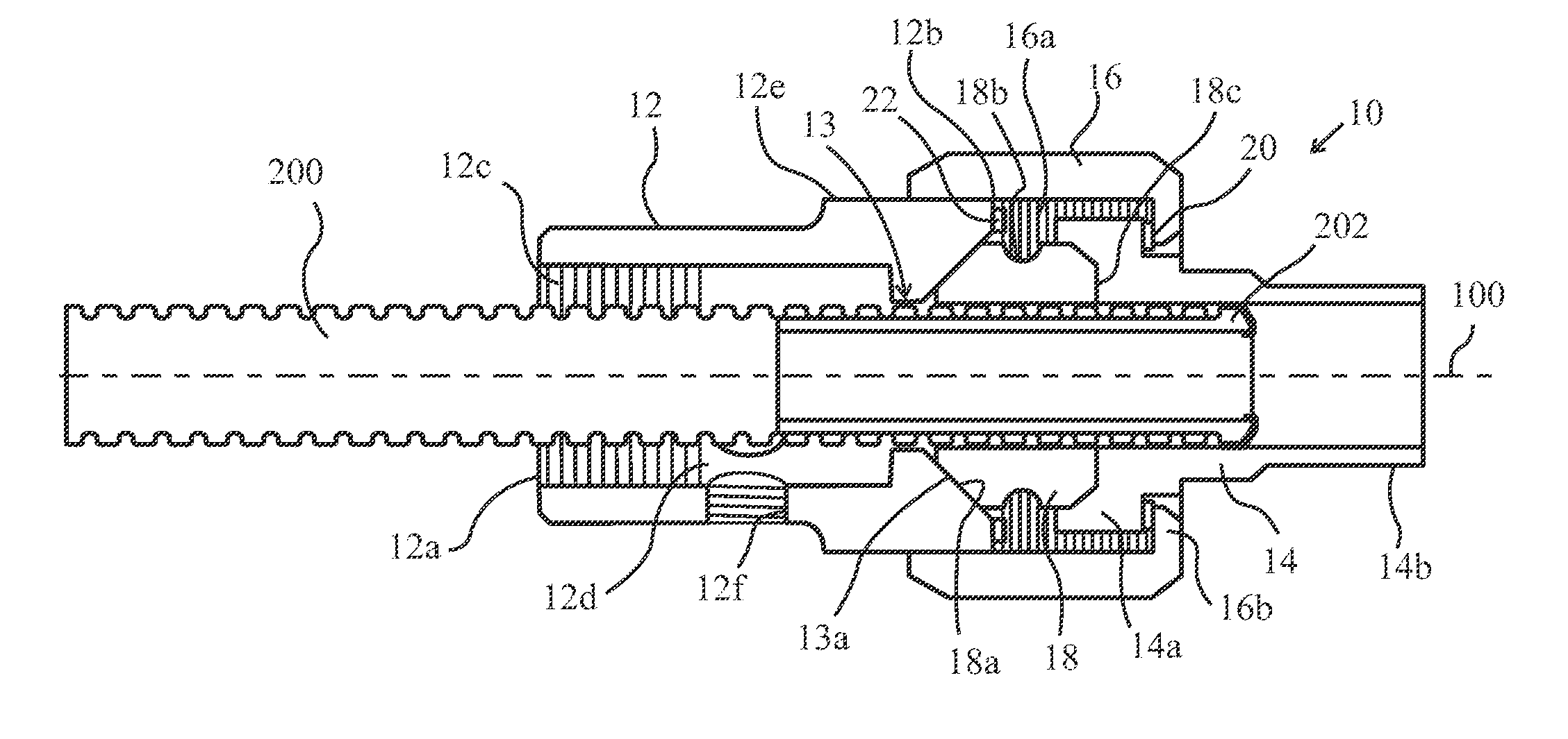
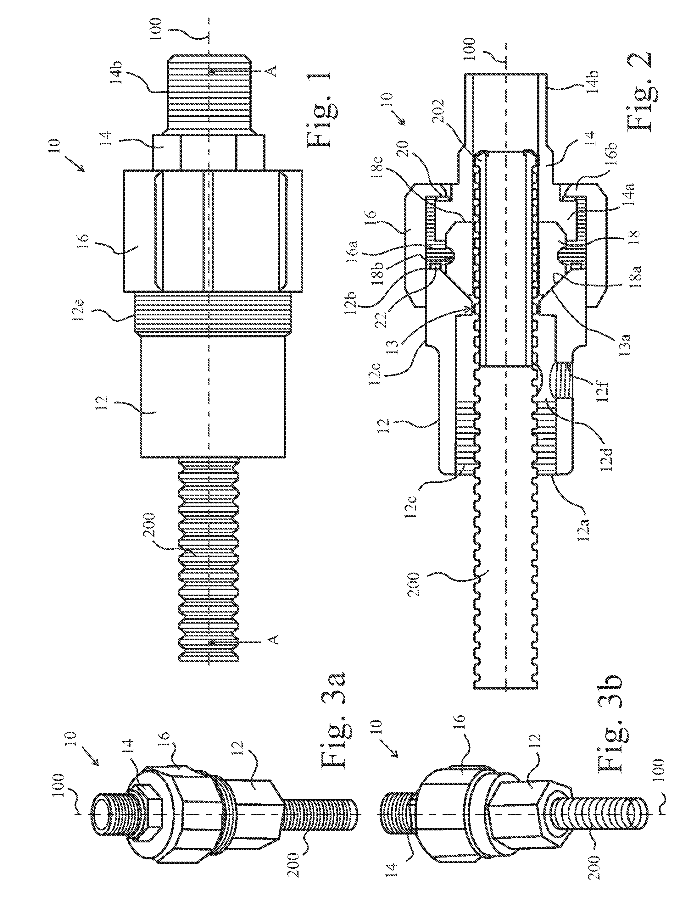
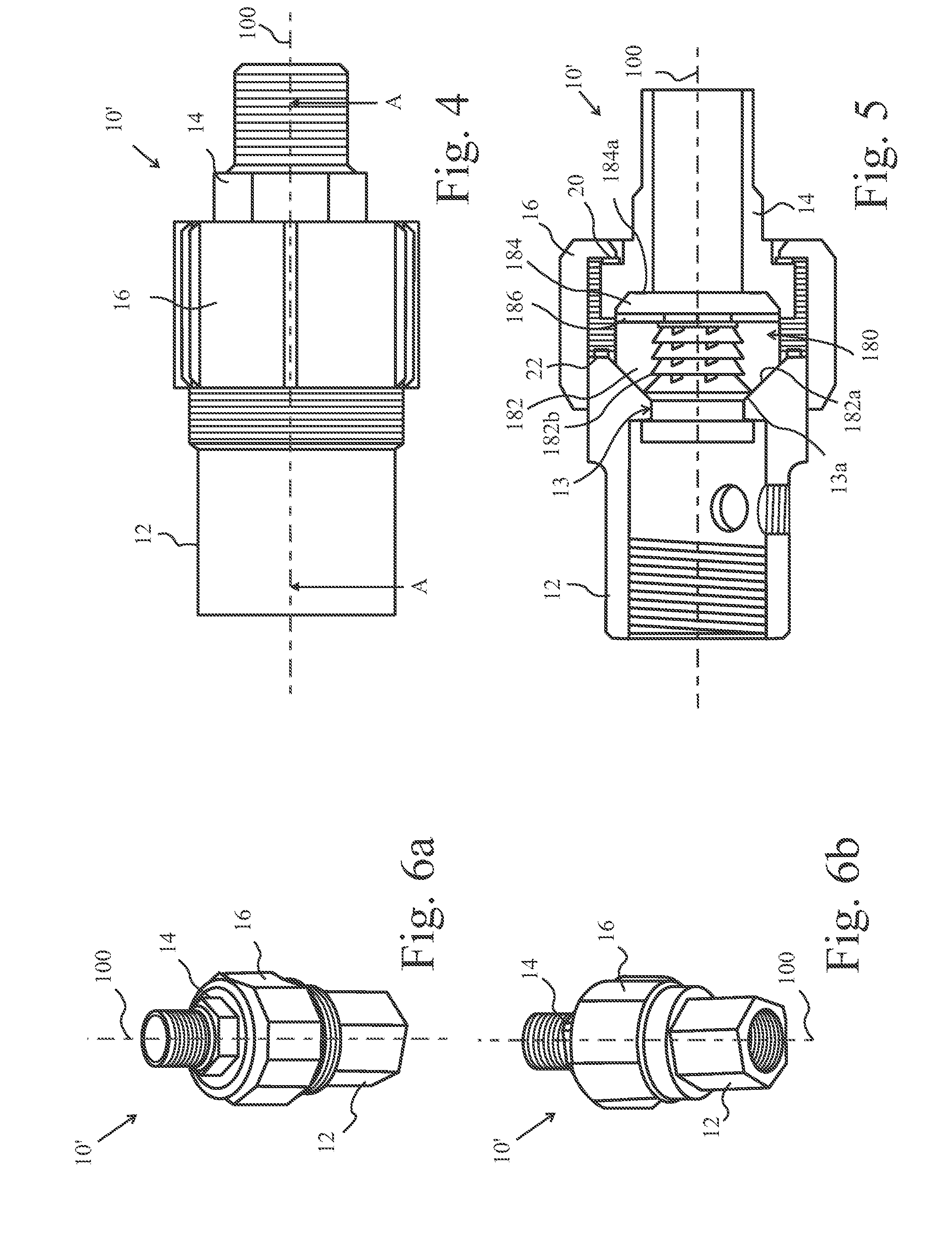
[0054]FIGS. 1 to 3 show a first embodiment 10 of a service head adaptor according to the present invention. The service head adaptor 10 has a body 12 with a first end 12a that is adapted to form a seal with a host pipe (not shown) of a service pipe. In the embodiments shown in the figures, the first end 12a has an internal screw thread 12c that is adapted to attach to and form a seal with the host pipe via a complementary screw thread. The body 12 has a bore 12d that extends along a longitudinal axis 100 and receives a lining pipe 200 of the service pipe when the host pipe is attached to the body 12. An internal annular flange 13 extends radially inwards from the body 12 (towards the longitudinal axis 100) and has an inclined surface 13a, where the direction of the incline is parallel to the longitudinal axis 100 towards the first end 12a of the body 12. A second end 12b of the body 12 is adapted to connect to and form a seal with a compression nut 16. In alternative embodiments, th...


PUM

PropertyMeasurementUnit
Temperatureaaaaaaaaaa
Lengthaaaaaaaaaa
Lengthaaaaaaaaaa

Abstract

An adaptor assembly to be fitted onto a service pipe comprising a host pipe lined with lining pipe is provided. The adaptor assembly includes a body to seal with the host pipe, a bore extending along a longitudinal axis of said body, and a compression element mountable on and axially and displaceable relative to the body. The adaptor assembly includes an axially translatable piston, an annular flange protruding into said bore, and a grip ring disposable between said piston and said flange and having an inner radial surface an outer radial surface of the lining pipe. A slip spacer is disposable between the compression element and the piston to transmit axial load prevent transmission of torque. The compression element is moveable to axially displace the piston causing the grip ring to bear against the inclined annular flange and grip radially inwardly against the outer radial surface.

Description

[0001]This invention relates to an adaptor for connecting a pipe to a fitting, in particular for connecting and sealing a service pipe (comprising a host pipe and a lining pipe) with a fitting.BACKGROUND[0002]It is becoming increasingly desirable and necessary to replace or reline metallic gas and water pipes with plastic pipes that are lighter, less susceptible to corrosion and easier to handle and manipulate. Indeed, various regulations and legislation set out strict rules and conditions regarding the nature of pipes that are situated in and around domestic buildings. For example, within UK houses there is the requirement that gas must be contained within pipes having a metal sheath.[0003]In some circumstances, old underground metal pipes are simply dug up to be replaced with plastic counterparts (using “open-cut” techniques). In other situations, where it is desirable, necessary or simply more convenient to leave the metallic pipes in place, they are relined with a plastic pipes....

Claims


Application Information

Patent Timeline
IPC IPC(8): F16L19/025
CPCF16L19/025Y10T29/49826F16L19/065
Inventor JENNER, ANDREWMUCKLE, DEREK
Owner RADIUS SYST LTD
Learn More