Flat-type single phase brushless DC motor

a brushless dc motor and flat-type technology, applied in the direction of magnetic circuits characterised by magnetic materials, magnetic circuit shapes/forms/construction, magnetic circuit rotating parts, etc., can solve the problems of deteriorating motor efficiency, difficult to fabricate stator cores for providing passageways, and wear of brushes, so as to improve motor efficiency and minimize the effect of magnetic field loss

Inactive Publication Date: 2007-06-21
DAEWOO ELECTRONICS CO LTD
View PDF5 Cites 32 Cited by
  • Summary
  • Abstract
  • Description
  • Claims
  • Application Information

AI Technical Summary

Benefits of technology

[0013] It is, therefore, an object of the present invention to provide a flat-type single phase BLDC motor having stator cores around which coils are wounded; and magnetic field focusing plates of enlarged areas which is installed at the stator cores to face a permanent magnet, wherein the stator cores are formed by compressing soft magnetic powder and serve to minimize a loss of magnetic fields that are generated from the coils to create a torque, and the magnetic field focusing plates serve to focus the magnetic fields on the permanent magnet, thus improving the motor efficiency.

Problems solved by technology

However, such a DC motor has a problem in that the brush is worn away.
However, it has been difficult to fabricate stator cores for providing passageways for the vertical magnetic fields by only laminating multiple silicon steel sheets of same shapes.
As a result, the magnetic field generated from the armature coils 11b and 11c could not be fully utilized in generating a torque for the rotation of the rotor 12, resulting in deterioration of the motor efficiency.

Method used


Image

  • Flat-type single phase brushless DC motor
  • Flat-type single phase brushless DC motor
  • Flat-type single phase brushless DC motor

Examples


Embodiment Construction

[0025] Hereinafter, exemplary embodiments of the present invention will be described in detail with reference to the accompanying drawings so that the present invention can be readily implemented by those skilled in the art.

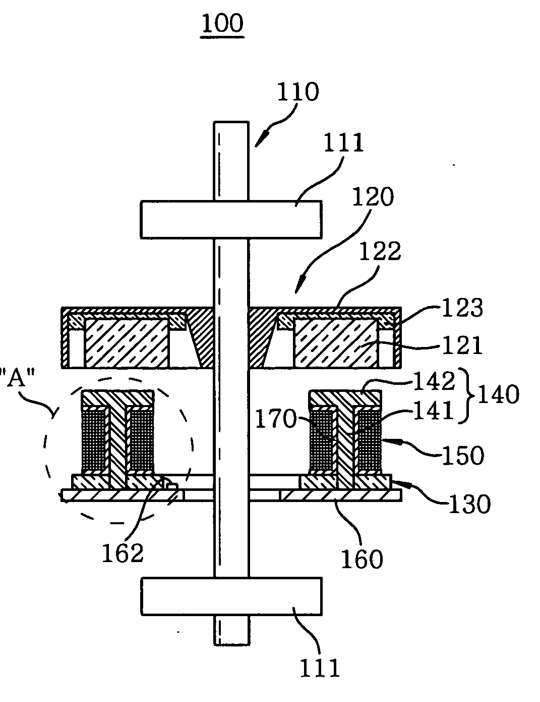
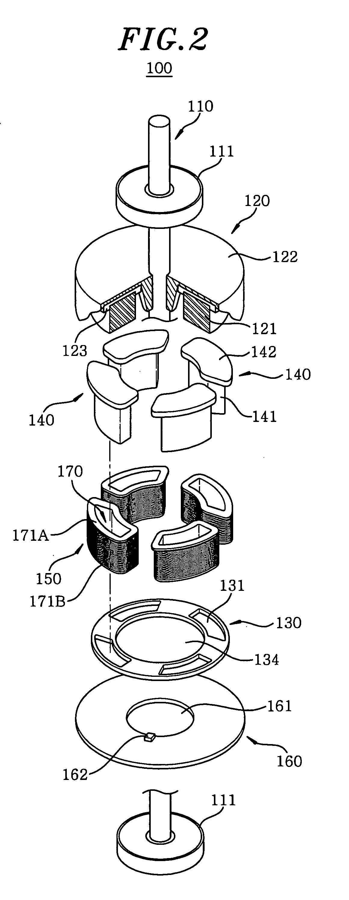
[0026]FIGS. 2 and 3 provide an exploded perspective view and a cross sectional view to illustrate a flat-type single phase BLDC motor assembly 100 in accordance with an embodiment of the present invention. FIG. 4 illustrates an enlarged view of “A” part of FIG. 3.

[0027] As shown, the flat-type single phase BLDC motor assembly 100 in accordance with the embodiment includes a shaft 110; a rotor 120 fastened to the shaft 110 and having a permanent magnet 121; a stator plate 130 installed below the rotor 120; a plurality of stator cores 140 arranged at the stator plate 130 at a regular interval in a circumferential direction of the stator plate 130 to face the permanent magnet 121; coils 150 wounded around the stator cores 140; and a control board 160 fastened to t...


PUM


Abstract

A flat-type single phase brushless direct current (BLDC) motor includes a rotor rotatably fixed to a shaft and having a permanent magnet attached to a lower side thereof; a stator plate installed below the rotor; a plurality of stator cores installed on the stator plate to face the permanent magnet, the stator cores including soft magnetic powder and arranged to be asymmetric with respect to a rotation radial direction of the rotor so as to determine a rotational direction of the rotor; and a multiplicity of coils each being wounded around corresponding one of the stator cores to form a magnetic field toward the permanent magnet.

Description

FIELD OF THE INVENTION [0001] The present invention relates to a flat-type single phase brushless DC (BLDC) motor; and, more particularly, to a flat-type single phase BLDC motor having stator cores around which coils are wounded, thus capable of improving motor efficiency by minimizing a loss of magnetic fields while focusing the magnetic fields to a permanent magnet. BACKGROUND OF THE INVENTION [0002] In general, a motor is a device that generates a rotary power by converting electric energy into mechanical energy, and it is widely employed in industrial apparatus as well as various household electronic appliances. The motor is largely divided into a direct current (DC) motor and an alternating current (AC) motor. [0003] In case of a DC motor which has a brush, an electric current is flown to a coil and rectified as a result of a contact between a commutator and the brush. However, such a DC motor has a problem in that the brush is worn away. Thus, to overcome such a drawback, a br...

Claims


Application Information

Patent Timeline
Patent Type & Authority Applications(United States)
IPC IPC(8): H02K21/12H02K1/00H02K1/22
CPCH02K1/148H02K21/24H02K1/2793H02K7/083H02K11/215H02K29/08H02K1/182H02K1/02H02K3/52
Inventor CHAE, JIN WON
Owner DAEWOO ELECTRONICS CO LTD
Why Eureka
Try Eureka