Super-regenerative receiver

a receiver and super-regenerative technology, applied in the direction of transmission, transmission monitoring, pulse automatic control, etc., can solve the problems of super-regenerative oscillators, sub-harmonic reactions, reverse isolation, etc., and achieve the effect of improving the characteristics related to the reception sensitivity and frequency selectivity thereo

Inactive Publication Date: 2007-06-21
SAMSUNG ELECTRO MECHANICS CO LTD
View PDF3 Cites 35 Cited by
  • Summary
  • Abstract
  • Description
  • Claims
  • Application Information

AI Technical Summary

Benefits of technology

[0015]The present invention has been made to solve the foregoing problems of the prior art and therefore an object of certain embodiments of the present invention is to provide a super-regenerative rece

Problems solved by technology

In the meantime, the super-regenerative oscillator has disadvantages such as reverse isolation, sub-harmonic reaction, low reception sensitivity and frequency selectivity.
However, if the bias current is too high, the receiver reacts even to undesired signals.
If the bias current is too low, the receiver may not react even to the desired signal.
Therefore, the bi

Method used


Image

  • Super-regenerative receiver
  • Super-regenerative receiver
  • Super-regenerative receiver

Examples


Embodiment Construction

[0027]Preferred embodiments of the present invention will now be described in detail with reference to the accompanying drawings. The invention may however be embodied in many different forms and should not be construed as limited to the embodiments set forth herein. Rather, these embodiments are provided so that this disclosure will be thorough and complete, and will fully convey the scope of the invention to those skilled in the art. In the drawings, the shapes and dimensions may be exaggerated for clarity, and the same reference numerals are used throughout to designate the same or similar components.

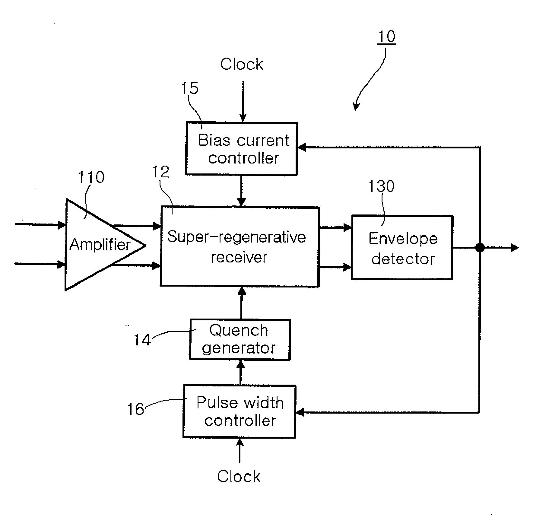
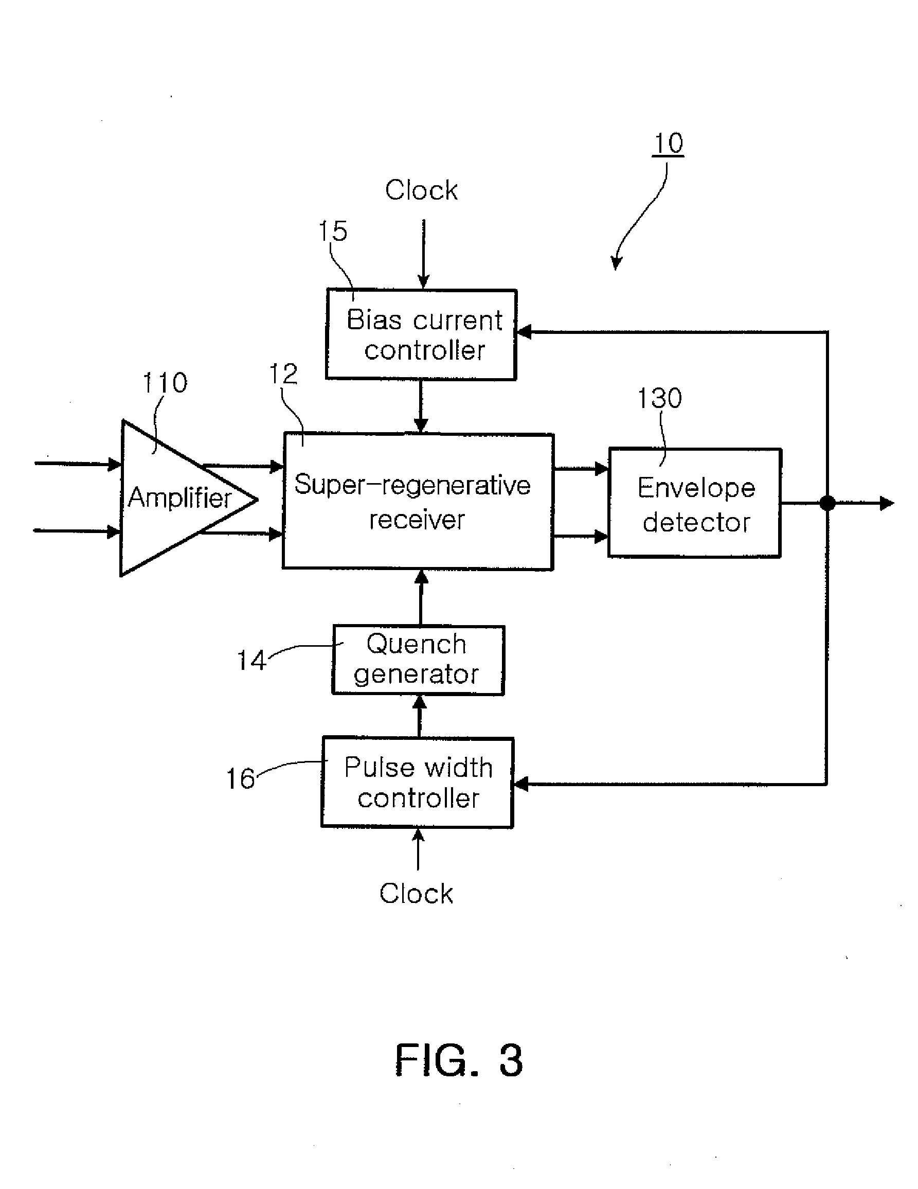
[0028]FIG. 3 is a block diagram illustrating a super-regenerative receiver according to an embodiment of the present invention.

[0029]Referring to FIG. 3, the super-regenerative receiver 10 according to an embodiment of the present invention includes an isolated preamplifier 110, a super-regenerative oscillator 12, a bias current controller 15, a pulse width controller 16 and a quench...


PUM


Abstract

A super-regenerative receiver including a super-regenerative oscillator is disclosed. The super-regenerative receiver includes a super-regenerative oscillator for generating an oscillation signal when receiving driving current exceeding a predetermined critical level. The receiver also includes a bias current controller for generating bias current according to an output of the super-regenerative oscillator, and a pulse width controller for receiving a predetermined clock and controlling a width of the clock according to the output of the super-regenerative oscillator. The super-regenerative receiver further includes a quench generator receiving the width-controlled clock from the pulse width controller and generating quench current that varies according to the pulse width of the clock. The driving current for oscillation equals to a sum of the bias current N-times multiplied and the quench current.

Description

CLAIM OF PRIORITY[0001]This application claims the benefit of Korean Patent Application No. 2005-125666 filed on Dec. 19, 2005, in the Korean Intellectual Property Office, the disclosure of which is incorporated herein by reference.BACKGROUND OF THE INVENTION[0002]1. Field of the Invention[0003]The present invention relates to a super-regenerative receiver including a super-regenerative oscillator, and more particularly, a super-regenerative receiver which precisely regulates an oscillation condition of a super-regenerative oscillator to improve reception sensitivity and frequency selectivity characteristics.[0004]2. Description of the Related Art[0005]In general, a super-regenerative receiver can be realized with lower costs and fewer components and operated with lower voltage compared to a homodyne or super-heterodyne receiver, and thus is suitable for a communication system that requires a low-cost and low-power receiver. Such a super-regenerative receiver includes a super-regene...

Claims


Application Information

Patent Timeline
IPC IPC(8): H03L7/099
CPCH03D11/06H03D11/08H03D11/02H03D11/04H04B1/06H04B1/26
Inventor KIM, JEONG HOONPARK, TAH JOONKIM, EUNG JUKIM, JOONG JIN
Owner SAMSUNG ELECTRO MECHANICS CO LTD
Why Eureka
Try Eureka