
Electromagnetic field tactile display interface and biosensor

a biosensor and tactile display technology, applied in the field of communication, can solve the problems of ineffective communication methods, inability to rely on verbal or visual based systems, and inability to accept and/or practice traditional verbal communication devices and systems such as phones,

Inactive Publication Date: 2007-06-21
UNIV OF CENT FLORIDA RES FOUND INC
View PDF17 Cites 76 Cited by
  • Summary
  • Abstract
  • Description
  • Claims
  • Application Information

AI Technical Summary

Benefits of technology

[0029] The computer sensor monitors the electromagnetic field change to determine the user's physiological status because the user's respiration causes a change in the position of the transducer contactor which results in the change in electromagnetic field. The computer sensor also monitors the electromagnetic field change to detect a predetermined pattern caused by the user physically moves the transducer contactor to cause the electromagnetic field change for communicating with the second user. A predetermined pattern is a series electromagnetic field changes caused by a series of user transducer contactor movement, such as a user taping the electromechanical transducer to cause the series of contactor movement. In an embodiment, the computer sensor detection includes detection of at least two different contactor movements, wherein the at least two different contactor movements includes long and short durations of electromagnetic field change, the long duration electromagnetic field change lasting longer in time than the short duration electromagnetic field change. Alternatively, the computer sensor detects simultaneous movement of more than one of the transducers in the array of electromechanical transducers.

Problems solved by technology

Communicating between individuals has generally required traditional verbal communication devices and systems such as phones, and the like, that are not acceptable and / or practical in certain environments.
A challenge in accomplishing this task is designing systems for providing information in diametrically opposed scenarios.
Current methods of communication do NOT effectively and covertly alert soldiers to the presence of threats while simultaneously cueing their locations.
Due to the constraints of these environments, solutions cannot rely on verbal or visually based systems.
Vision and visual cues are not generally available and always practical in military battle environments.
Also, use of light-based systems during night operations negates the advantage gained through the use of night vision equipment.
Speech and verbal cues are not always available or practical in covert military operations.
Over the years attempts have been made at providing 3-dimensional spatial information both aurally and tactually, but they have achieved limited success.
In addition, the ability of the auditory system to discriminate among sounds located at different elevations is poor.
It is unlikely that soldiers will be able to send and receive verbal communications while simultaneously attending to an auditory alarm amidst the noise and stress of combat.
In environments such as during battles and the like, human senses such as hearing, vision and smell can be overpowered and are impaired.
For example, troops may not be able to hear verbal commands and verbal communications when explosions and artillery fire is underway.
Tactile sensors can be useful for providing some information but still fail by themselves to effectively communicate desired communications between parties.
However, none of the above references disclose an apparatus or method for communicating qualitative and quantitative tactile cues while also monitoring user vital signs that is usable for covert operation without broadcasting signals that may be intercepted by unfriendly individuals within range.

Method used


Image

  • Electromagnetic field tactile display interface and biosensor
  • Electromagnetic field tactile display interface and biosensor
  • Electromagnetic field tactile display interface and biosensor

Examples


Embodiment Construction

[0038] Before explaining the disclosed embodiments of the present invention in detail it is to be understood that the invention is not limited in its applications to the details of the particular arrangements shown since the invention is capable of other embodiments. Also, the terminology used herein is for the purpose of description and not of limitation.

[0039] The following is a list of the reference numbers used in the drawings and the detailed specification to identify components:

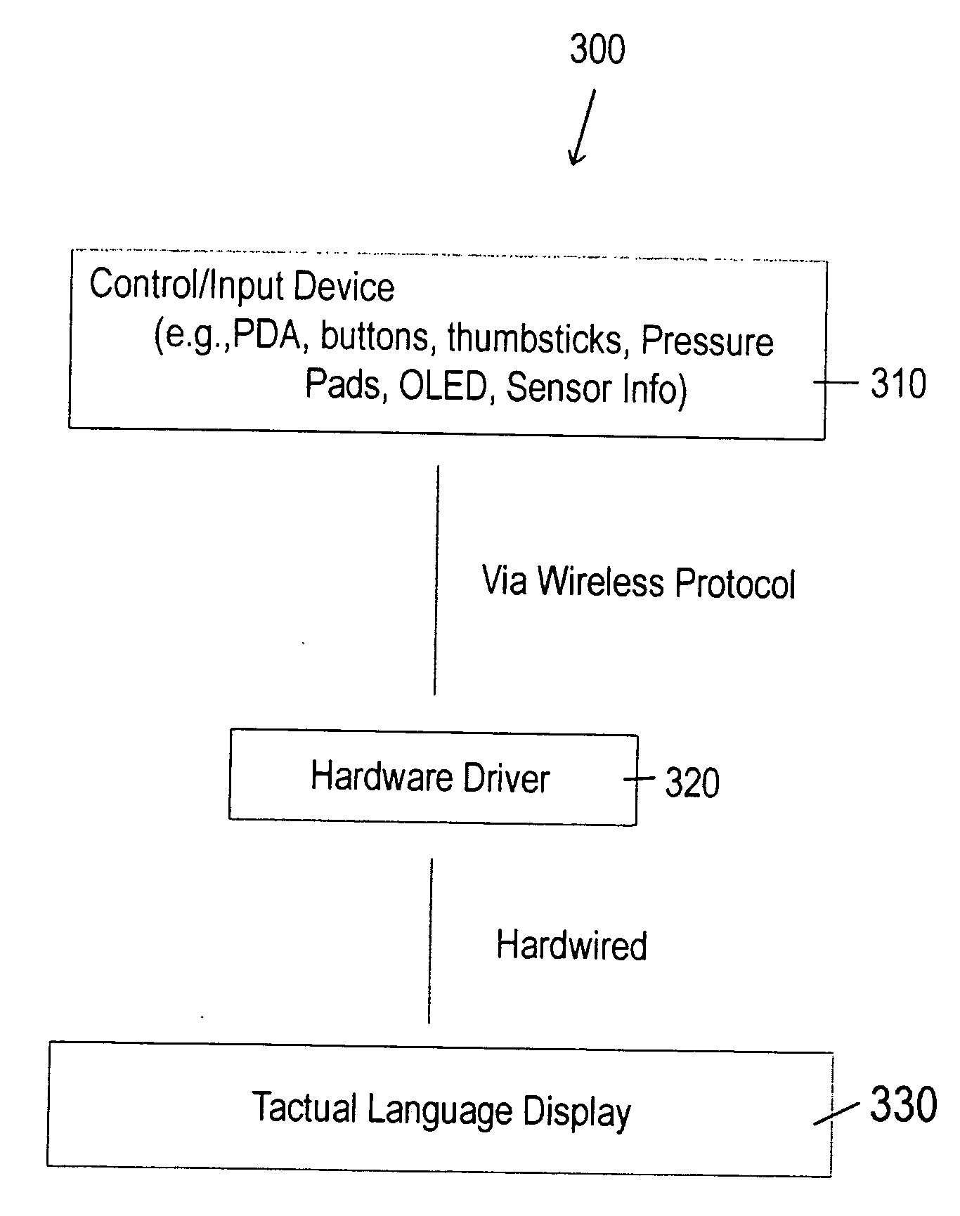
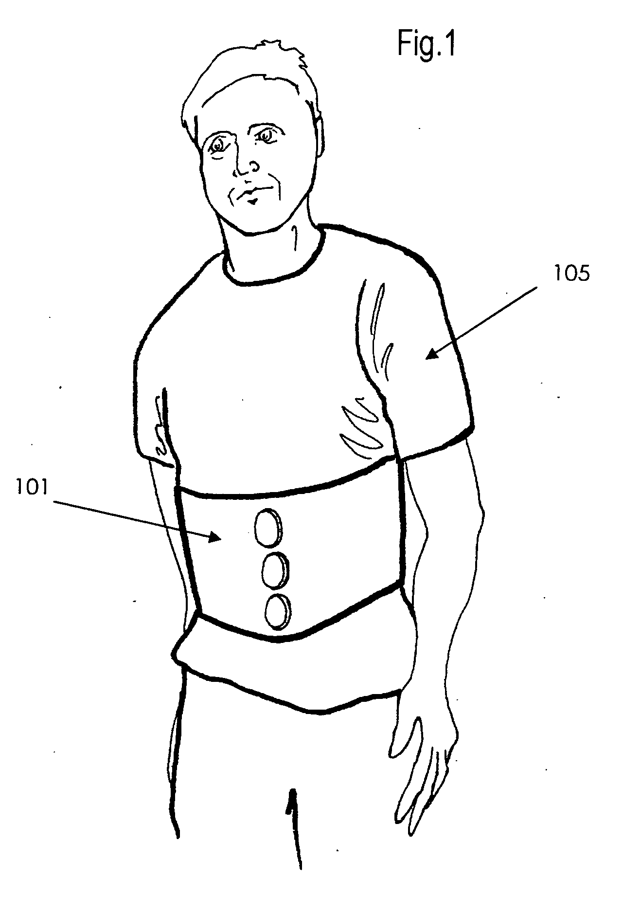
100vibrotactile waistbelt101elastic belt110electromechanical transducers120vertical array ofelectromechanical transducers130cabling140computer driver150power supply160power cord170electromagnetic field sensor200manually activated input device210tactile cue switches220position switches300hardware configuration310input device320hardware driver330tactile language display

[0040] One way of communicating through the sense of touch is via transducers, speaker-like devices that vibrate against the skin. Trad...


PUM


Abstract

Tactile communication methods, systems and devices for wireless touch communication which include an array of electromechanical transducers each independently capable of producing a vibration for communicating qualitative and quantitative tactile cues to a user, at least one electromagnetic field sensor coupled with at least one of the array of transducers for monitoring a change in an electromagnetic field of the array of electromechanical transducers and producing an output signals when a change is detected, wherein a change in a position of a transducer contactor produces the change in the electromagnetic field and a vibrotactile waistbelt for housing the array of electromechanical transducers and sensors, wherein the vibrotactile waistbelt is worn by a user to receive and send wireless touch communication respectively from and to a remotely located controller.

Description

[0001] This application is a continuation-in-part of co-pending U.S. patent application Ser. No. 11 / 250,878 filed on Oct. 14, 2005 and was funded at least in part by Defense Advanced Research Projects Agency (DARPA) TACOM Contract No. DAAE07-03-C-L143.FIELD OF INVENTION [0002] This invention relates to communications, and in particular to systems, methods, devices, and apparatus using tactile type transducers to be worn by users such as military personal, emergency services, sports participants and referees, gaming users, virtual reality users and the like, as a communication language for communicating information such as instructions, cueing and navigation information between parties. BACKGROUND AND PRIOR ART [0003] Communicating between individuals has generally required traditional verbal communication devices and systems such as phones, and the like, that are not acceptable and / or practical in certain environments. For example, getting situation-relevant information to dismounte...

Claims


Application Information

Patent Timeline
IPC IPC(8): H04B3/36
CPCG06F1/163G06F3/016G09B21/003
Inventor GILSON, RICHARD D.BRILL, J. CHRISTOPHER
Owner UNIV OF CENT FLORIDA RES FOUND INC
Learn More