Antenna device

a technology of antenna device and filler, which is applied in the direction of anti-theft devices, loop antennas with ferromagnetic cores, transportation and packaging, etc., can solve the problems of long production process, insufficient filling and curing filler b>6/b>, and insufficient water proofing performance of conventional antenna devices b>10/b>, so as to achieve the effect of simplifying the manufacturing process

Inactive Publication Date: 2007-06-21
PANASONIC CORP
View PDF5 Cites 31 Cited by
  • Summary
  • Abstract
  • Description
  • Claims
  • Application Information

AI Technical Summary

Benefits of technology

[0013] The antenna device disclosed in the present invention comprises: the first waterproof provided on the outer periphery of a stopper which is to seal the case opening tightly; and the second waterproof provided on the inner periphery of the stopper, wherein the first waterproof and the second waterproof are disposed on locations approximately the same distance from the top surface of the stopper. Since the first and second waterproofs can prevent water immersion into the case from outside, and therefore the filler that has been needed previously is no longer required, the invention can provide an antenna device with a simplified manufacturing process.

Problems solved by technology

However, merely filling and curing filler 6 is not sufficient to obtain good water proofing performance.
As described above, conventional antenna device 10 needs a long time and complicated processes for production.

Method used


Image

  • Antenna device
  • Antenna device
  • Antenna device

Examples


Embodiment Construction

[0023] The exemplary embodiments of the present invention are described with reference to FIGS. 1 to 5.

EXEMPLARY EMBODIMENTS

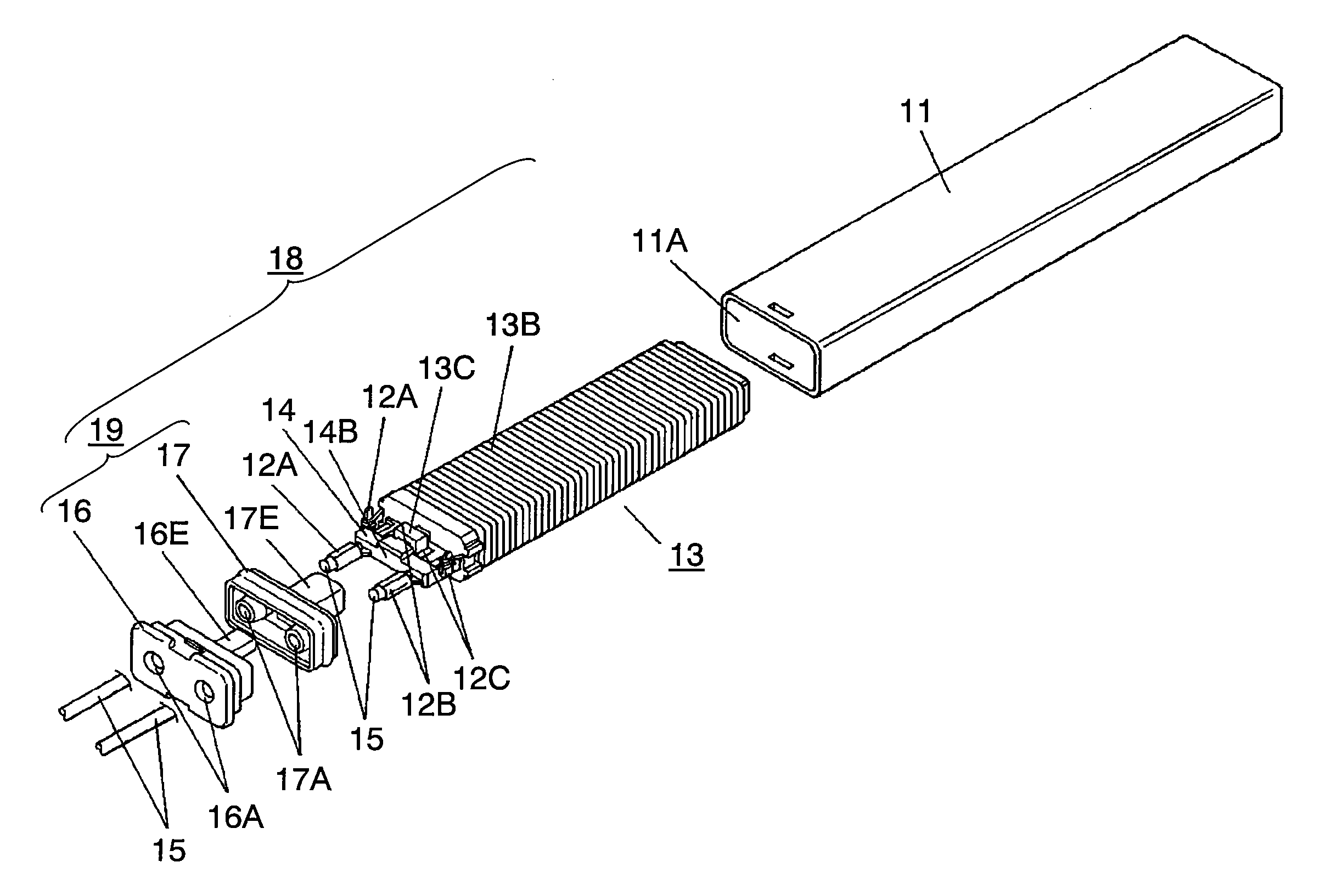
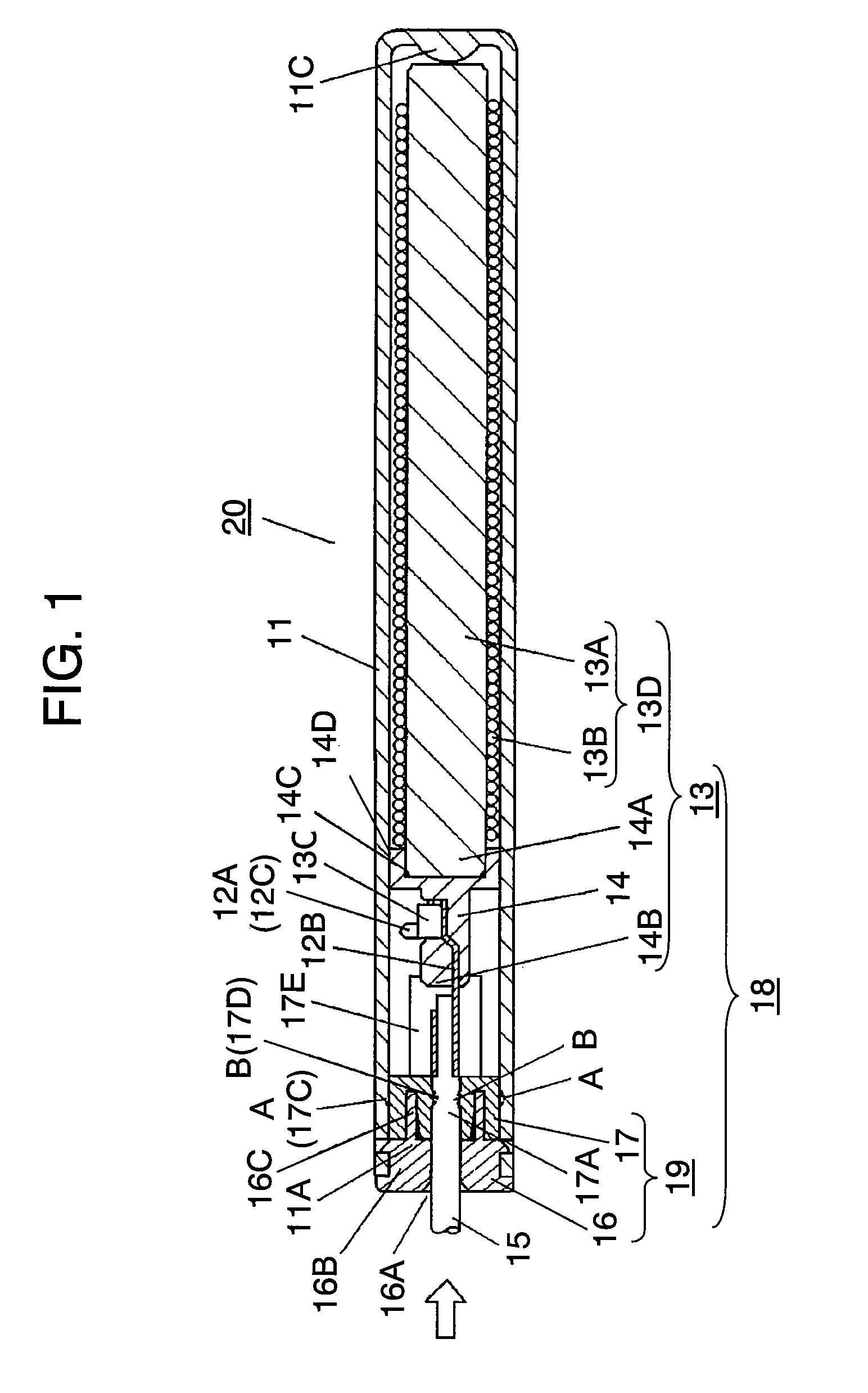
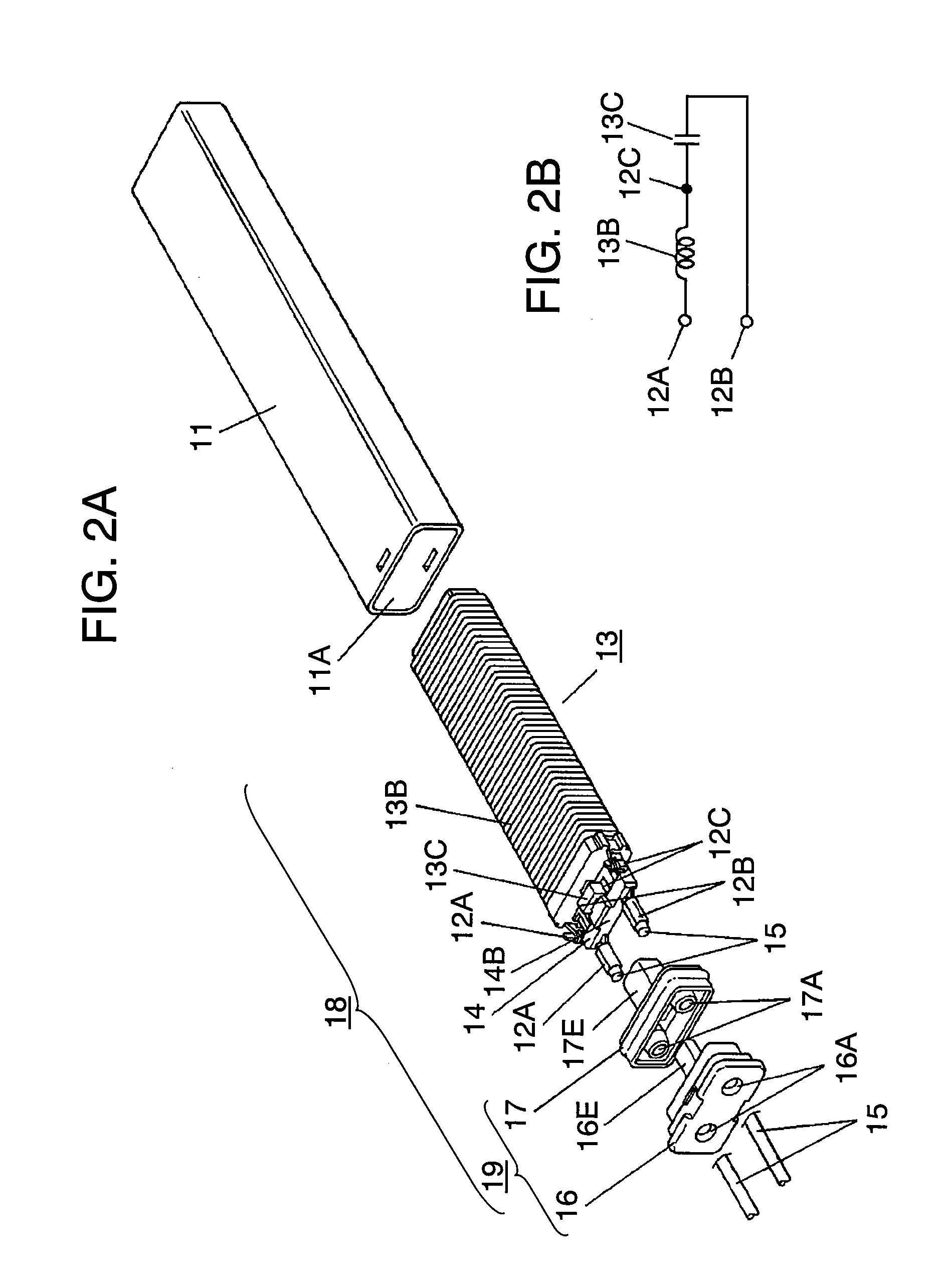
[0024] FIGS. 1 to 3 illustrate an antenna device used in the exemplary embodiments of the present invention. FIG. 1 shows a cross-sectional view of antenna device 20, FIG. 2A shows an exploded perspective view of antenna device 20, and FIGS. 3A and 3B show enlarged cross-sectional views of essential parts of antenna device 20.

[0025] Substantially cylindrical shaped case 11 is formed from materials having good properties in heat resistance and mechanical strength such as polybutylene terephthalate (PBT) or the like. Antenna part 13 is housed into case 11 through opening 11A formed on the left hand side of case 11.

[0026] Antenna part 13 includes: ferrite core 13A or a magnetic material, coil 13B wound around the outer periphery of ferrite core 13A, and capacitor 13C connected in series with coil 13B.

[0027] The integration of ferrite core 13A and coil 13B is ...


PUM


Abstract

An antenna device having a substantially cylindrical shaped case to house the antenna part and a stopper to seal a case opening tightly, wherein the stopper has the first waterproof on the outer periphery to contact the case and the second waterproof on the inner periphery to contact the lead wires. The first waterproof and the second waterproof are disposed on a same location. The present invention can provide the antenna device capable of preventing water immersion into the case simply and reliably without using any filler.

Description

FIELD OF THE INVENTION [0001] The present invention relates to an antenna device for use in a remote-control system to control locking / unlocking vehicle doors or the like from a distance through a radio communication using a mobile device. BACKGROUND ART [0002] In recent years, a remote-control system has being widely used to control locking / unlocking vehicle doors from a distance by communicating between a mobile device and an antenna device installed in the vehicle. [0003] The conventional antenna device for use in such a remote-control system is described with reference to FIG. 6. FIG. 6 shows a cross-sectional view of conventional antenna device 10. Substantially box-like case 1 formed from a non-conducting material has opening 1A in the top surface, and extended terminals 2A and 2B are embedded in the left hand side of case 1 as shown in FIG. 6. Extended terminals 2A and 2B are molded integrally with case 1. [0004] Case 1 includes antenna part 3. Antenna part 3 includes: ferrit...

Claims


Application Information

Patent Timeline
Patent Type & Authority Applications(United States)
IPC IPC(8): H01Q7/08B60R11/02B60R16/02B60R25/01B60R25/24H01Q1/02
CPCH01Q1/3241H01Q1/3291H01Q1/42H01Q7/08
Inventor SHIGEMOTO, HIDEKI
Owner PANASONIC CORP
Why Eureka
Try Eureka