Pointing device adapted for small handheld devices

Active Publication Date: 2007-06-21
PIXART IMAGING INC
View PDF63 Cites 52 Cited by
  • Summary
  • Abstract
  • Description
  • Claims
  • Application Information

AI Technical Summary

Benefits of technology

[0011] The present invention includes a display device having a puck, a display screen, and a controller. The puck moves on a first surface that includes a puck field of motion defined thereon, the puck field of motion being divided into a pointing region and a function region. The controller determines a position of the puck within the field of motion. The display screen has first and second display modes, the display screen displaying a two-dimensional scene in the first display mode and a sub-scene of the two-dimen

Problems solved by technology

While the mouse has provided a satisfactory solution to the pointing device problem in the desktop PC market, a similarly successful device is not available for hand-held devices such as cellular telephones.
These devices lack a sufficiently large flat surface near the keypad or screen over which a mouse can be moved.
In addition, the need to carry a separate pointing device makes the mouse less than ideal for these applications.
In addition, the pointing device must operate in a limited workspace and fit within the form factor of the hand held device.
Both of these devices fall far short of satisfying the above requirements.
Unfortunately, the button can only move a small amount; hence, the displacement of the button cannot be mapped directly into a displacement in the cursor position on the computer display.
This limitation is particularly evident in tasks that require small, precise movements such as drawing in a comp

Method used


Image

  • Pointing device adapted for small handheld devices
  • Pointing device adapted for small handheld devices
  • Pointing device adapted for small handheld devices

Examples


Embodiment Construction

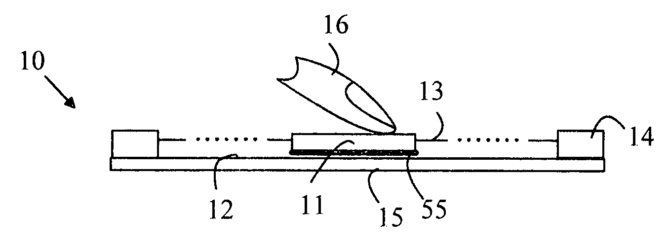
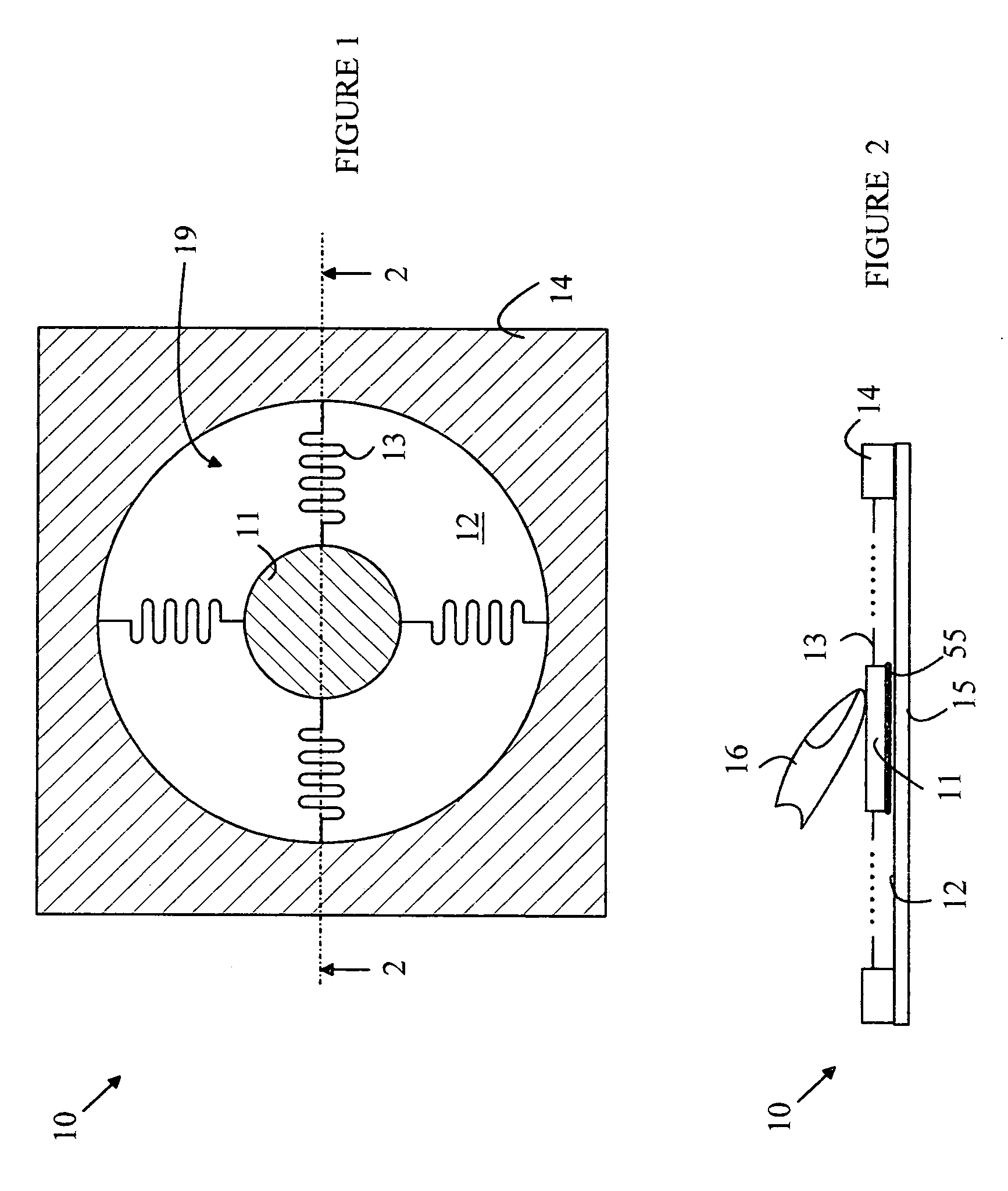
[0028] The manner in which the present invention provides its advantages can be more easily understood with reference to FIGS. 1 and 2, which illustrate a puck-based pointing device 10 as taught in the above-described patent applications. FIG. 1 is a top view of pointing device 10, and FIG. 2 is a cross-sectional view of pointing device 10 through line 2-2 shown in FIG. 1. Pointing device 10 includes a puck 11 that moves over a surface 12 of a substrate 15 within a puck field of motion 19 in response to a lateral force applied to puck 11. The force is typically applied to puck 11 by a user's finger. Puck 11 includes a pressure sensing mechanism that measures the vertical pressure applied to puck 11. When the sensed pressure exceeds a predetermined threshold, the cursor tracking function is activated and the cursor moves on the screen in a direction and distance determined by the motion of the puck. In addition, pointing device 10 includes a sensing mechanism for determining the posi...


PUM


Abstract

A display device having a puck, a display screen, and a controller is disclosed. The puck moves in a puck field of motion on a surface, the field of motion being divided into a pointing region and a function region. The controller determines a position of the puck within the field of motion. The display screen has first and second display modes, the display screen displaying a two-dimensional scene in the first display mode and a sub-scene of the two-dimensional scene in the second display mode. A cursor that moves within the sub-scene in a manner controlled by the puck position in the pointing region is displayed in the second mode. The controller causes the display scene to change between modes when the puck moves between regions. The sub-scene position moves in response to the position of the puck in the function region in the first display mode.

Description

BACKGROUND OF THE INVENTION [0001] Modern computer operating systems and graphics programs require a pointing device for controlling the position of a cursor on the computer display. Likewise, handheld devices such as personal information managers and cell phones would also benefit from the inclusion of such a pointing device. For desktop PCs, the most successful pointing device is the “mouse”. A mouse is a hand held object that is moved over a flat surface near the keyboard to control the motion of a cursor on the computer display. The direction and distance over which the mouse is moved determines the direction and distance the cursor moves on the display. A conventional mouse provides a rigid object that a user can move with great precision. For a desktop computer, the mouse provides a satisfactory solution to the pointing problem. On the occasion when the workspace is not large enough to provide a path over which the mouse can move and accommodate a desired cursor movement on th...

Claims


Application Information

Patent Timeline
IPC IPC(8): G09G5/08
CPCG06F1/1626G06F1/169G06F3/03548G06F3/0481G06F3/0485
Inventor HARLEY, JONAH
Owner PIXART IMAGING INC
Why Eureka
Try Eureka