Liquid-droplet jetting apparatus

a jetting apparatus and liquid drop technology, applied in printing, other printing apparatus, etc., can solve the problems of strict use conditions of ink-jet printers by users, and achieve the effects of reducing the effect of jetting performance, stirring liquid effectively, and preventing a decline in printing performan

Active Publication Date: 2007-06-21
BROTHER KOGYO KK
View PDF4 Cites 18 Cited by
  • Summary
  • Abstract
  • Description
  • Claims
  • Application Information

AI Technical Summary

Benefits of technology

[0027] In the liquid-droplet jetting apparatus of the present invention, the controller may continue to impart the vibration to the meniscus of the liquid till just before the carriage arrives at a subsequent jetting area. In this case, since the controller imparts the vibration to the meniscus of the liquid till just before the subsequent jetting area of the carriage, it is possible to stir assuredly the thickened liquid with the new liquid, and to prevent a decline in the printing performance in the subsequent operation.
[0028] In the liquid-droplet jetting apparatus of the present invention, the controller may impart the vibration to the meniscus of the liquid for a fixed period of time after starting a supply of the drive pulses to the actuator. In this case, a time for suppressing the remained vibrations of the meniscus on a nozzle opening surface which is vibrating, is made available due to the no-jetting drive, and it is possible to reduce an effect on jetting performance.
[0029] The liquid-droplet jetting apparatus of the present invention, may further include a flushing mechanism which performs flushing of the head. In this case, it is possible to eliminate assuredly the thickened liquid from the head.
[0030] The liquid-droplet jetting apparatus of the present invention may further include a cartridge which accommodates the liquid, and which is exchangeable. The controller may i

Problems solved by technology

However, with an improvement in speeding up of an ink-jet printer, condition

Method used


Image

  • Liquid-droplet jetting apparatus
  • Liquid-droplet jetting apparatus
  • Liquid-droplet jetting apparatus

Examples


Embodiment Construction

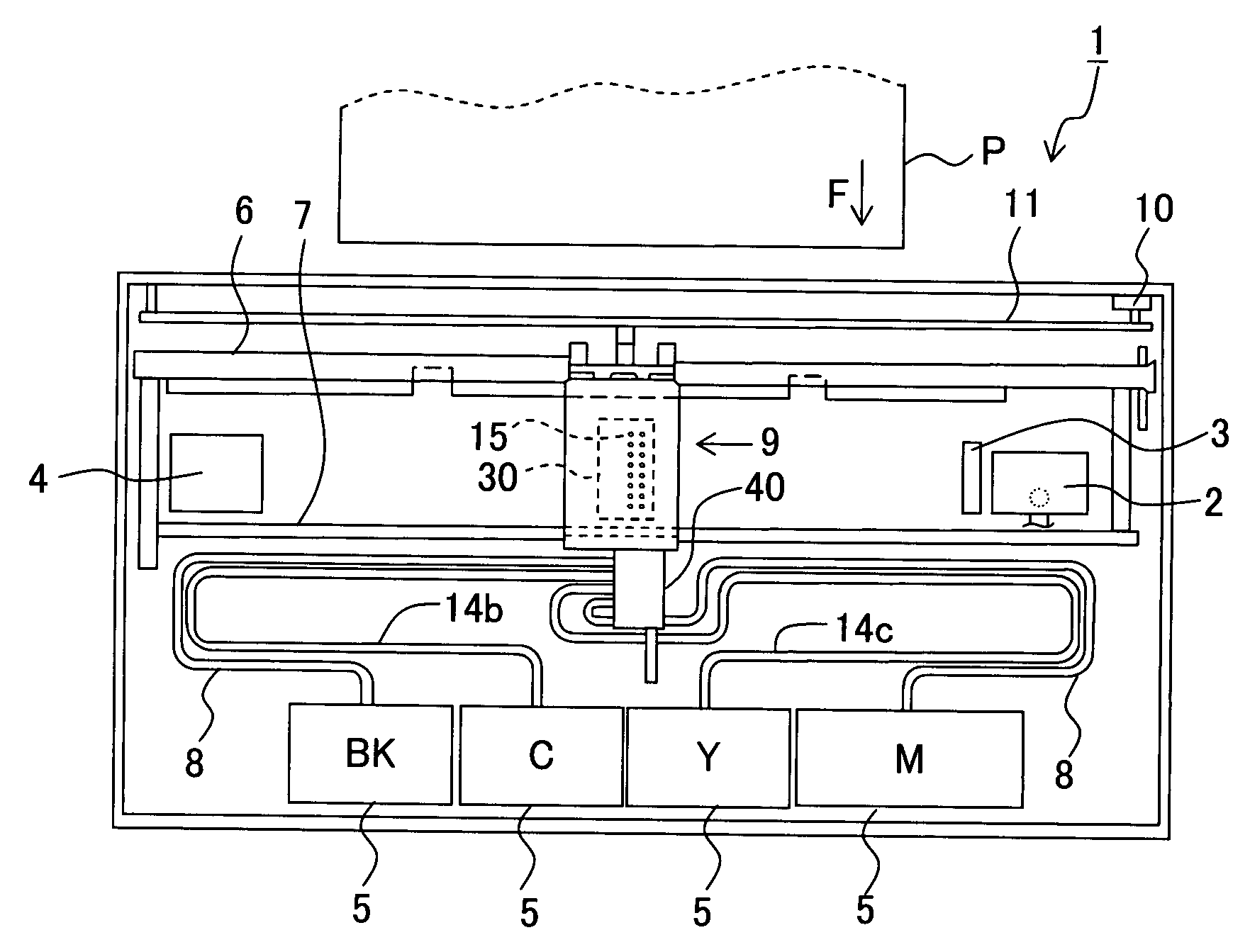
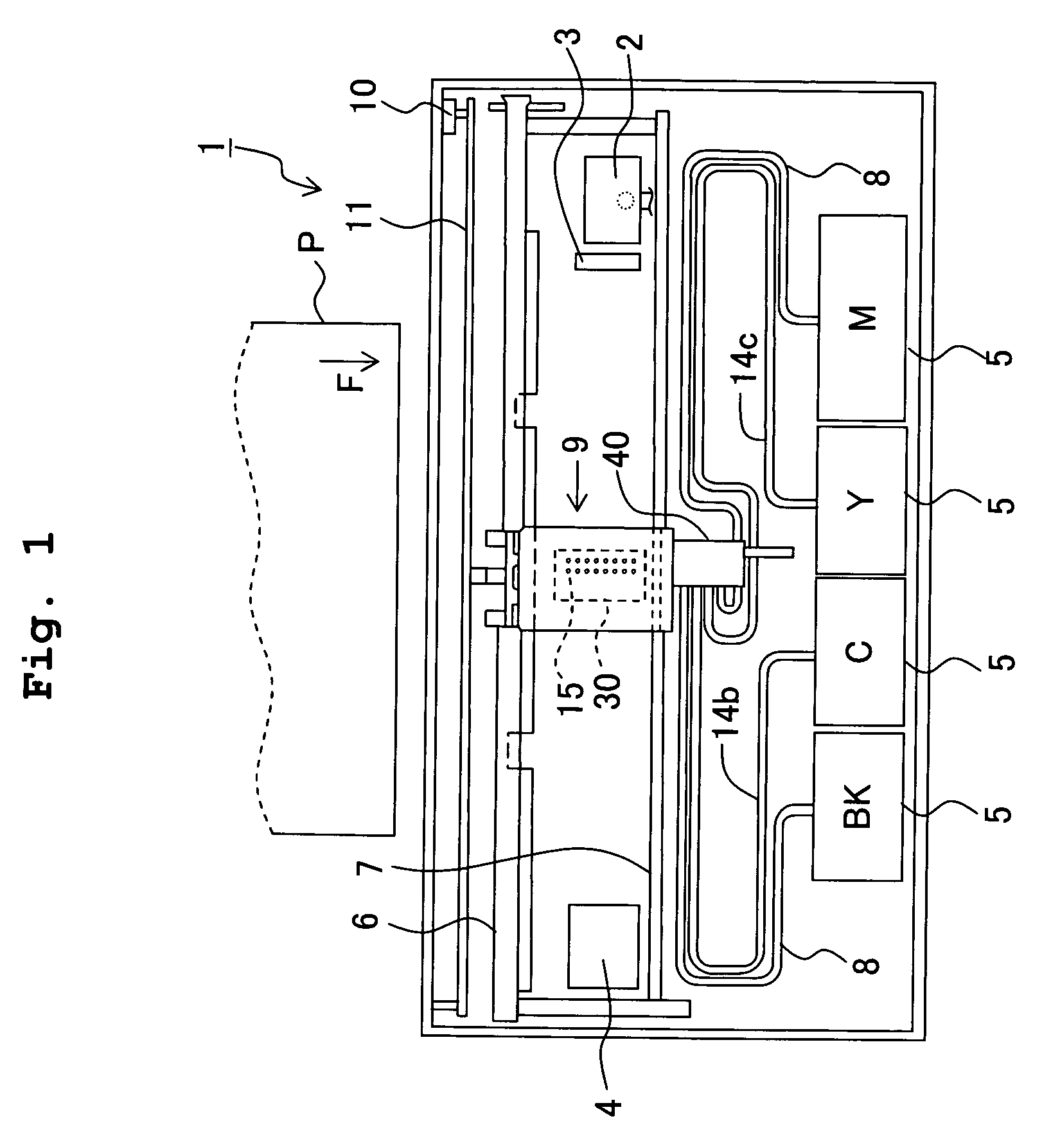
[0042] An embodiment of the present invention will be described below by referring to the accompanying diagrams. Firstly, an ink-jet printer 1 which is an example of the liquid-droplet jetting apparatus of the present invention will be described below with referring to FIG. 1 and FIG. 2. In the following description, a side toward which the ink is jetted is a lower surface and a direction of discharge is a downward direction, and a side opposite to the ink discharge is an upper surface and a direction is an upward direction. Moreover, in FIG. 1, a left-end side in the diagram is a left direction, a right-end side is a right direction, a lower side in the diagram is a frontward direction, and an upper side in the diagram is a rearward direction.

[0043] As shown in FIG. 1, the ink-jet printer 1 is provided with two guide shafts 6 and 7 inside the ink-jet printer 1. A head holder which serves as a carriage 9 is installed on the guide shafts 6 and 7. A recording head 30 which performs r...


PUM


Abstract

A liquid-droplet jetting apparatus such as an ink-jet printer makes a meniscus of an ink in a nozzle vibrate by applying a no-jetting drive pulse which does not jet the ink. An operation of outputting two no-jetting drive pulses in one cycle is repeated for 100 to 150, and then stopped for 100 to 150 cycles. A pulse width Tp of the no-jetting drive pulses, an interval Tw between two no-jetting drive pulses, and a time AL in which a pressure wave in an ink channel is propagated one way are set to be in a range 0.1 AL≦Tp≦0.2 AL, and 0.2 AL≦Tw≦4.5 AL. Accordingly, it is possible to prevent assuredly, thickening of a liquid such as an ink in the nozzle, and to reduce a generation of a defect in jetting of a liquid droplet.

Description

CROSS REFERENCE TO RELATED APPLICATION [0001] The present application claims priority from Japanese Patent Application No. 2005-362823, filed on Dec. 16, 2005, the disclosure of which is incorporated herein by reference in its entirely. BACKGROUND OF THE INVENTION [0002] 1. Field of the Invention [0003] The present invention relates to a liquid-droplet jetting apparatus which jets a liquid droplet. For example, the present invention relates to a control for preventing an occurrence of a printing defect which is caused due to drying of a liquid near an opening of a nozzle, in a liquid-droplet jetting apparatus such as an ink-jet printer. [0004] 2. Description of the Related Art [0005] A conventional liquid-droplet jetting apparatus such as an ink-jet printer includes a carriage on which a recording head having a plurality of nozzles discharging an ink is mounted. The recording head includes pressure chambers which communicate with the nozzles respectively, and an actuator which appli...

Claims


Application Information

Patent Timeline
IPC IPC(8): B41J2/045
CPCB41J2/04563B41J2/04581B41J2/04596B41J2/16526B41J2002/14217B41J2002/14225B41J2002/16502
Inventor SEKIGUCHI, YASUHIRO
Owner BROTHER KOGYO KK
Why Eureka
Try Eureka