Image pickup apparatus and reproducing apparatus

Inactive Publication Date: 2007-06-21
CANON KK
View PDF21 Cites 20 Cited by
  • Summary
  • Abstract
  • Description
  • Claims
  • Application Information

AI Technical Summary

Benefits of technology

[0009] The present invention is directed to solving the problems described above, and provides an i

Problems solved by technology

Moreover, even if a frame is extracted from a moving image to obtain a digital still image, the resolution of the frame image taken by using the pipeline for the video recording mode is low.
The method does not allow a user, during moving image reproduction, to extract a high-resolution frame image at a desired scene from a compressed moving image.
Also, an image processi

Method used


Image

  • Image pickup apparatus and reproducing apparatus
  • Image pickup apparatus and reproducing apparatus
  • Image pickup apparatus and reproducing apparatus

Examples


first exemplary embodiment

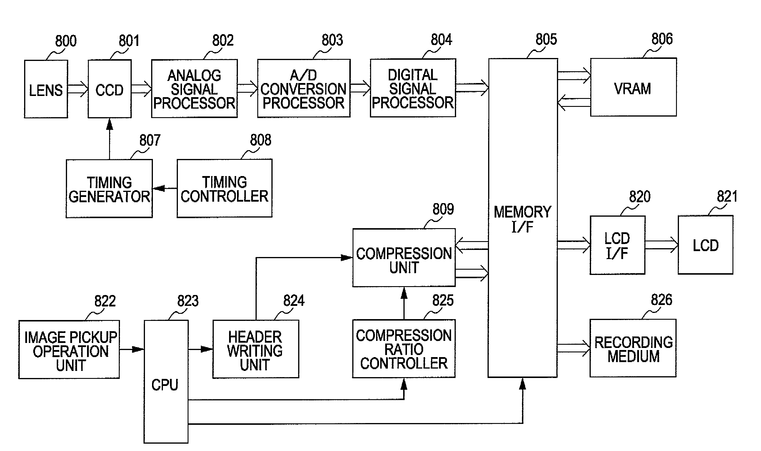
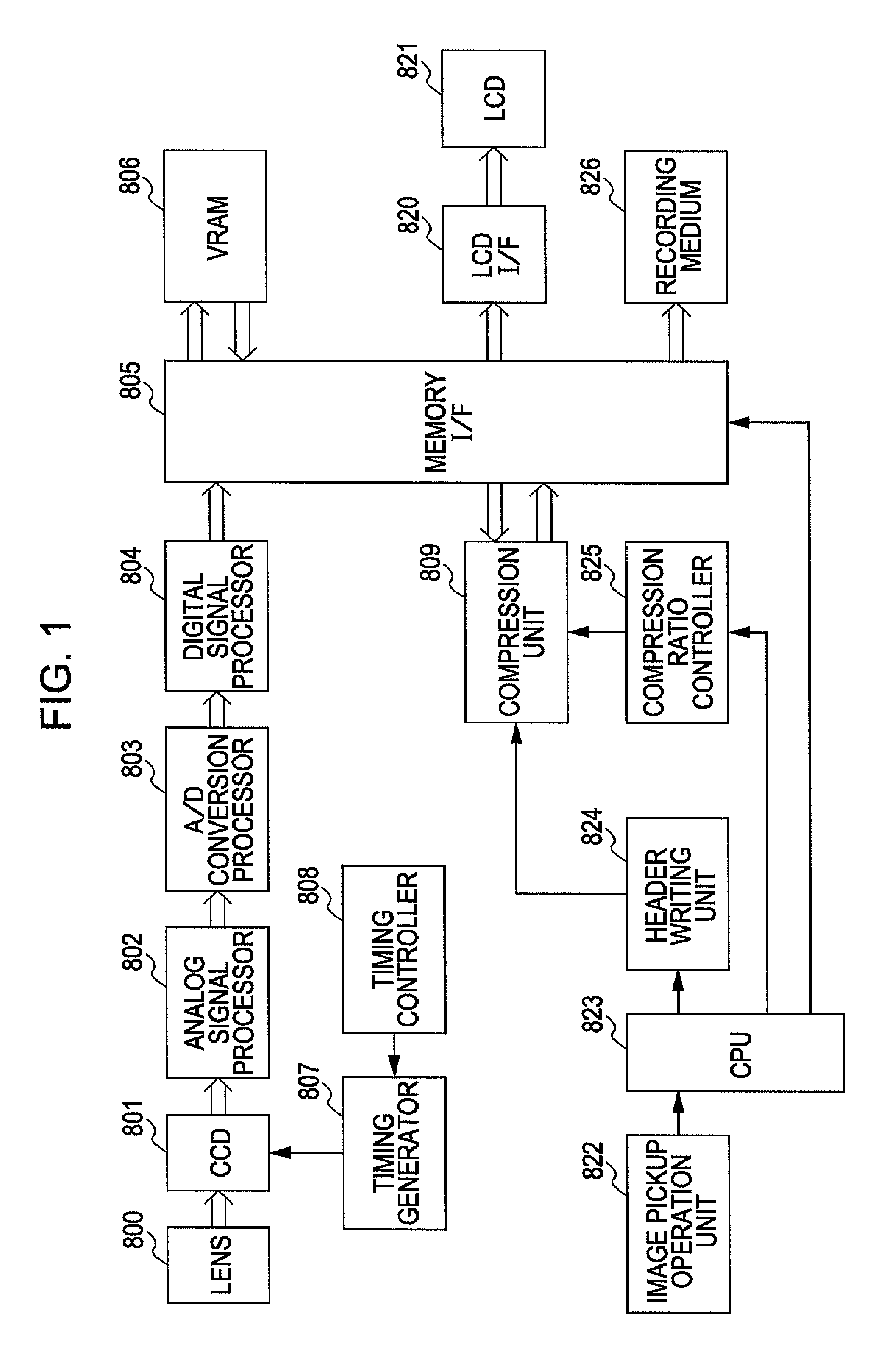
[0033]FIG. 1 is a block diagram according to a first exemplary embodiment of the present invention, and illustrates an exemplary configuration of an image pickup apparatus capable of changing a compression ratio during moving image shooting. FIG. 5 is a flowchart illustrating processing steps where a shooting mode is changed during moving image shooting in the first exemplary embodiment.

[0034] First, the image pickup apparatus of the present exemplary embodiment will be described with reference to FIG. 1. In FIG. 1, a subject optical image entered through a lens 800 is photoelectrically converted by a charge-coupled device (CCD) 801 into an electric signal. On the basis of a drive control signal input from a timing generator 807, the CCD 801 captures the subject optical image for a predetermined period of time.

[0035] At the same time, the CCD 801 sends an image signal having been converted into an electric signal to an analog signal processor 802 according to a read control signal...

second exemplary embodiment

[0053]FIG. 8 is a block diagram according to a second exemplary embodiment of the present invention, and illustrates an exemplary configuration of an image pickup apparatus capable of changing a compression method during moving image shooting. FIG. 9 is a flowchart illustrating processing steps where a shooting mode is changed during moving image shooting in the second exemplary embodiment.

[0054] First, a configuration of the image pickup apparatus of the present exemplary embodiment will be described with reference to FIG. 8. In FIG. 8, a subject optical image entered through a lens 100 is photoelectrically converted by a CCD 101 into an electric signal.

[0055] On the basis of a drive control signal input from a timing generator 107, the CCD 101 captures the subject optical image for a predetermined period of time. At the same time, the CCD 101 sends an image signal having been converted into an electric signal to an analog signal processor 102 according to a read control signal (...

third exemplary embodiment

[0071]FIG. 10 is a block diagram according to a third exemplary embodiment of the present invention, and illustrates an exemplary configuration of an image pickup apparatus capable of changing a frame resolution during moving image shooting. FIG. 11 is a flowchart illustrating processing steps where a shooting mode is changed during moving image shooting in the third exemplary embodiment.

[0072] First, a configuration of the image pickup apparatus of the present exemplary embodiment will be described with reference to FIG. 10. In FIG. 10, a subject optical image entered through a lens 300 is photoelectrically converted by a CCD 301 into an electric signal. On the basis of a drive control signal input from a timing generator 307, the CCD 301 captures the subject optical image for a predetermined period of time. At the same time, the CCD 301 sends an image signal having been converted into an electric signal to an analog signal processor 302 according to a read control signal input fr...


PUM


Abstract

When a shooting mode is changed from a non-super-resolution mode to a super-resolution mode, an image pickup apparatus lowers a compression ratio in a compression unit. On the other hand, when the shooting mode is changed from the super-resolution mode to the non-super-resolution mode, the image pickup apparatus raises a compression ratio in the compression unit.

Description

BACKGROUND OF THE INVENTION [0001] 1. Field of the Invention [0002] The present invention relates to image pickup apparatuses and reproducing apparatuses, and particularly to techniques for changing a compression ratio during moving image shooting. [0003] 2. Description of the Related Art [0004] Today, many commercially available cameras are configured to be capable of shooting both digital videos and digital still photographs. However, different pipelines are typically provided for a video recording mode and a digital still image mode. Therefore, a user is required to switch back and forth between the video recording mode and the digital still image mode during shooting. Moreover, even if a frame is extracted from a moving image to obtain a digital still image, the resolution of the frame image taken by using the pipeline for the video recording mode is low. [0005] Japanese Patent Laid-Open No. 2003-283921 (hereinafter referred to as “Patent Document 1”) discloses a method for simu...

Claims


Application Information

Patent Timeline
IPC IPC(8): H04N5/76H04N5/225H04N5/232H04N19/107H04N19/162H04N19/189H04N19/50
CPCH04N5/772H04N5/907H04N9/7921H04N19/172H04N19/46H04N19/115H04N19/577H04N19/60H04N19/107H04N19/154H04N19/162H04N19/59H04N19/61
Inventor WATANABE, YOSHINORI
Owner CANON KK
Why Eureka
Try Eureka