Method and system for synchronizing opto-mechanical filters to a series of video synchronization pulses and derivatives thereof

a technology of optomechanical filters and video synchronization pulses, applied in the field of method and system for synchronizing optomechanical filters to a series of video synchronization pulses and derivatives thereof, can solve problems such as the reduction of image extinction ratio, achieve the improvement of visual quality and perceived depth, and reduce image extinction ratio.

Inactive Publication Date: 2007-06-21
IBM CORP
View PDF10 Cites 45 Cited by
  • Summary
  • Abstract
  • Description
  • Claims
  • Application Information

AI Technical Summary

Benefits of technology

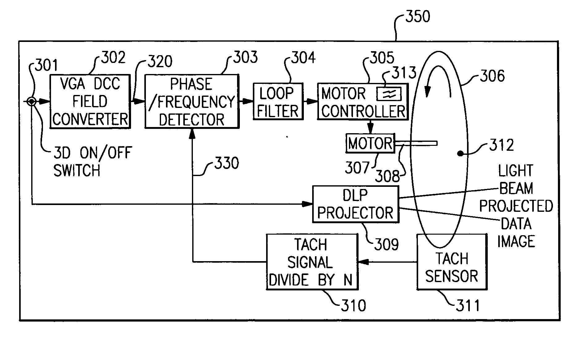
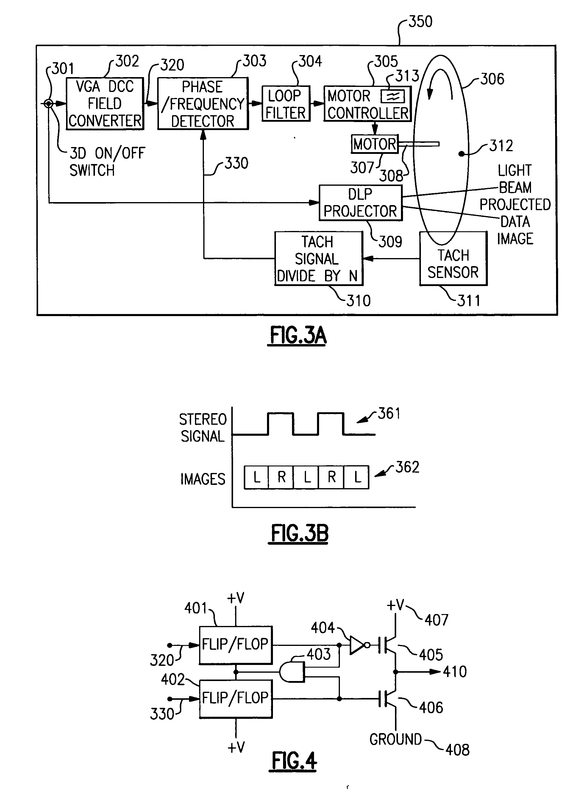
[0029] In the case of a stereographic projector that places a single linear polarizing wheel in the light path of the projector to impart a desired polarization state onto the projected light, it is obvious that the polarized light will have a continuously variable transmission axis as the wheel rotates. This causes undesirable affects such as ghosting and decreased image extinction ratio. The polarizing is synchronized in frequency and phase to a signal that indicates which perspective view is currently being displayed by the projector. For implementations where the line

Problems solved by technology

This causes undesirable affects such as gho

Method used


Image

  • Method and system for synchronizing opto-mechanical filters to a series of video synchronization pulses and derivatives thereof
  • Method and system for synchronizing opto-mechanical filters to a series of video synchronization pulses and derivatives thereof
  • Method and system for synchronizing opto-mechanical filters to a series of video synchronization pulses and derivatives thereof

Examples


Embodiment Construction

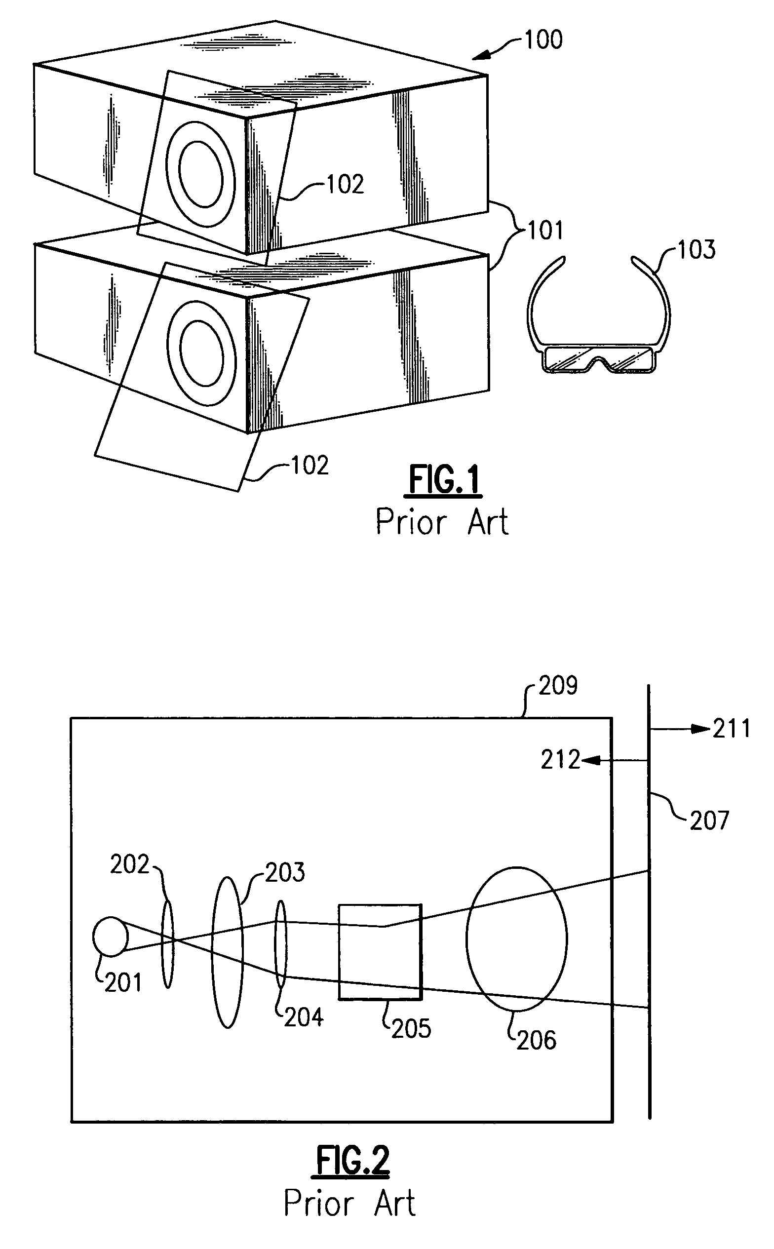
[0056] For generating three dimensional (“3D”) images, two separate two dimensional (“2D”) images representing two lines of sight of a 3D scene are required-one 2D image viewed by each of a person's eyes exclusive to each eye. The apparatus illustrated in FIG. 1 is a traditional 3D projection system that uses a two projection device to simultaneously overlap the images and achieve a stereoscopic display.

[0057] With reference to FIG. 1, there is illustrated a prior art three dimensional projection system 100. This prior art utilizes two separate projectors 101 each projecting an identical scene but each with a slightly different perspective corresponding to the different perspectives between a person's left eye and right eye lines of sight. Polarized glass (or other material) filters 102 are placed in the paths of the projected light beams from each of the two projectors. The polarization angles of these filters are offset 90° from each other. In order for a viewer to perceive a thr...


PUM


Abstract

A method and system for synchronizing rotating machinery or other electromechanical actuator devices to a series of sync pulses derived from a video stream comprising point optimized control laws.

Description

CROSS REFERENCES TO RELATED APPLICATIONS [0001] U.S. patent applications Ser. No. 11 / ______, entitled “Lumen optimized stereo projector using a plurality of polarizing filters”; and [0002] Ser. No. 11 / ______, entitled “Stereographic projection apparatus with passive eyewear utilizing a continuously variable polarizing element”; and [0003] Ser. No. 11 / ______, entitled “Universal stereographic trigger peripheral for electronic equipment”; and [0004] Ser. No. 11 / ______, entitled “Signal Synthesizer for Periodic Acceleration and Deceleration of Rotating Optical Devices”; and [0005] Ser. No. 11 / ______, entitled “Noise Immune Optical Encoder for High Ambient Light Projection Imaging Systems”; and [0006] Ser. No. 11 / ______, entitled “Method to synchronize stereographic hardware to sequential color rendering apparatus”, all filed concurrently herewith are assigned to the same assignee hereof and contain subject matter related, in certain respect, to the subject matter of the present applica...

Claims


Application Information

Patent Timeline
IPC IPC(8): G03B21/14H04N9/12G02B30/25H04N13/363
CPCG03B9/10G03B35/22G03B35/26H04N13/0438H04N13/0454H04N13/0459H04N13/0497H04N13/341H04N13/363H04N13/359H04N13/398
Inventor DECUSATIS, CASIMER M.TRIFILO, TIMOTHY M.
Owner IBM CORP
Why Eureka
Try Eureka