Cooled turbine blade

Active Publication Date: 2007-06-21
RAYTHEON TECH CORP
View PDF20 Cites 36 Cited by
  • Summary
  • Abstract
  • Description
  • Claims
  • Application Information

AI Technical Summary

Benefits of technology

[0008] In accordance with the present invention, a turbine engine component broadly comprises an airfoil portion, a plurality of cooling passages within the a

Problems solved by technology

These components are subjected to the harsh environment immediately downstream of the combustor where fuel and air are mixed and burned in a constant pressure process.
Th

Method used


Image

  • Cooled turbine blade
  • Cooled turbine blade
  • Cooled turbine blade

Examples


Example

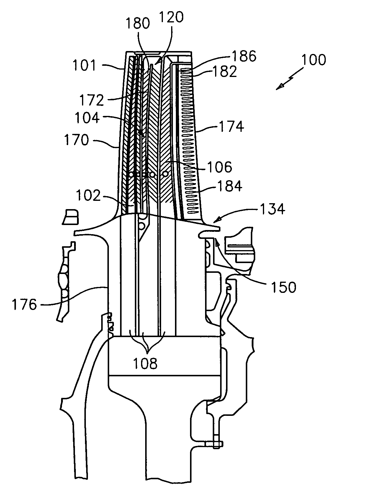
[0018] The present invention relates to a new design for a component, such as a cooled turbine blade, to be used in gas turbine engines. The component of the present invention comprises a gas turbine airfoil containing unique internal and external geometries which contribute to the aim of providing long-term operation. The turbine component contains unique features to enhance the overall performance of the turbine blade.

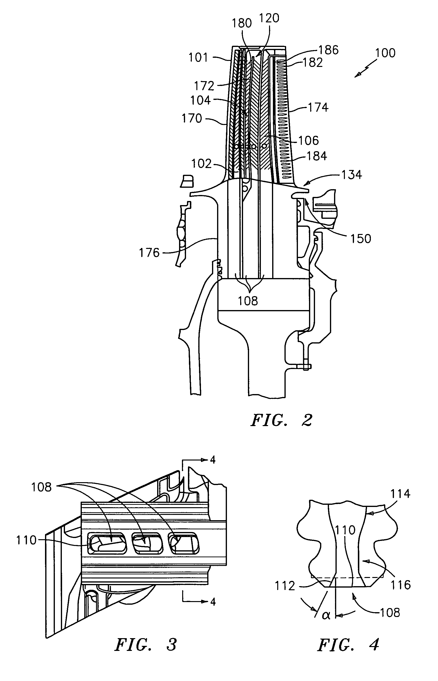
[0019] Referring now to FIG. 2, there is shown a turbine blade 100 in accordance with the present invention. The turbine blade 100 is provided with an airfoil portion 101, preferably having three independent cooling circuits 102, 104, and 106 to address the separate needs of the airfoil portion leading edge 170, the main airfoil body 172, and the airfoil trailing edge region 174. Each of the cooling circuits 102, 104, and 106 may be provided with a plurality of trip strips or other devices 180 for creating turbulence in a cooling fluid flowing through the circuits 1...


PUM


Abstract

A turbine engine component, such as a turbine blade, has an airfoil portion, a plurality of cooling passages within the airfoil portion with each of the cooling passages having an inlet for a cooling fluid. Each inlet has a flared bellmouth inlet portion. The turbine engine component may further have a dirt funnel at the tip of the airfoil portion, a platform with at least one beveled edge, and an undercut trailing edge slot.

Description

BACKGROUND OF THE INVENTION [0001] (1) Field of the Invention [0002] The present invention relates to a turbine engine component, such as a cooled turbine blade, for gas turbine engines. [0003] (2) Prior Art [0004] Cooled gas turbine blades are used to provide power in turbomachines. These components are subjected to the harsh environment immediately downstream of the combustor where fuel and air are mixed and burned in a constant pressure process. The turbine blades are well known to provide power by exerting a torque on a shaft which is rotating at high speed. As a result, the turbine blades are subjected to a myriad of mechanical stress factors resulting from the centrifugal forces applied to the part. In addition, the turbine blades are typically cooled using relatively cool air bled from the compressor. These cooling methods necessarily cause temperature gradients within the turbine blade, which lead to additional elements of thermal-mechanical stress within the structure. [000...

Claims


Application Information

Patent Timeline
IPC IPC(8): F01D5/18
CPCF01D5/081F01D5/143F01D5/145F01D5/187F01D5/20F05D2240/122F05D2240/304F05D2250/185F05D2240/80F05D2260/607F05D2250/232F05D2250/712F05D2250/314
Inventor CHARBONNEAU, ROBERTDOWNS, JAMESGREGG, SHAWNHARRIS, WESLEYKHANDROS, NATALIALEVINE, JEFFREY R.ORNDOFF, PAULPALMER, STEVEPIETRASZKIEWICZ, EDWARD F.ROELOFFS, NORMANSTOCKTON, RICHARDWIDMER, WANDAWILLIAMS, DAGNY
Owner RAYTHEON TECH CORP
Why Eureka
Try Eureka