

Method and system for exterior protection of an aircraft
a technology for aircraft and exterior protection, applied in the direction of aircraft static dischargers, weaving, synthetic resin layered products, etc., can solve the problems of affecting the service life of aircraft, so as to reduce the number of microcracks, improve the structural durability, and reduce the effect of weigh
Inactive Publication Date: 2007-06-21
THE BOEING CO
View PDF9 Cites 58 Cited by
- Summary
- Abstract
- Description
- Claims
- Application Information
AI Technical Summary
Benefits of technology
The present invention relates to a new type of material called expandable aluminum foils (EAA). These foils have been developed over time due to their superior strength, durability, and ability to resist weather damage. They also offer excellent resistance against corrosion and prevent cracking under heavy loads. Additionally, they reduce weight without compromising the required properties like color quality. Overall, these EAA materials improve the performance and lifespan of high-use commercial airplanes.
Problems solved by technology
The technical problem addressed in this patent is the need for an improved method and structure for protecting the exterior surfaces of aircraft against lightning strikes that is lighter, more cost-effective, and less susceptible to corrosion, microcracking, and environmental degradation than existing methods. Existing methods, such as co-curing metal wires or fabrics with composite materials, have limitations due to the extreme environment of high-use commercial aircraft. The patent seeks to provide a solution that can provide the desired characteristics of lightning protection, while being lightweight and easy to maintain and repair.
Method used
View moreImage
Smart ImageViewing Examples

Examples
example 1
[0033] enamel 2 mils, intermediate coat 0.3-0.5 mil, primer 0.5 mil, Hexcel BBA Polymat / M50 surfacing film, Alcore 2 mil EAF, Hexcel 6080 / M50 isolator (1 ply);
example 2
[0034] enamel 2 mils, intermediate coat 0.3-0.5 mil, primer 0.5 mil, Hexcel BBA Polymat / M50 surfacing film, EAF 4 mil, Hexcel 6080 / M50 isolator (1 ply);
example 3
[0035] enamel 2 mils, intermediate coat 0.3-0.5 mil, primer 0.5 mil, Hexcel BBA Polymat / M50+30 gsm additional resin surfacing film, Alcore 4 mil EAF, Hexcel 6080 / M50 isolator (1 ply);
Login to View More PUM
| Property | Measurement | Unit |
|---|---|---|
| Thickness | aaaaa | aaaaa |
| Thickness | aaaaa | aaaaa |
| Thickness | aaaaa | aaaaa |
Abstract
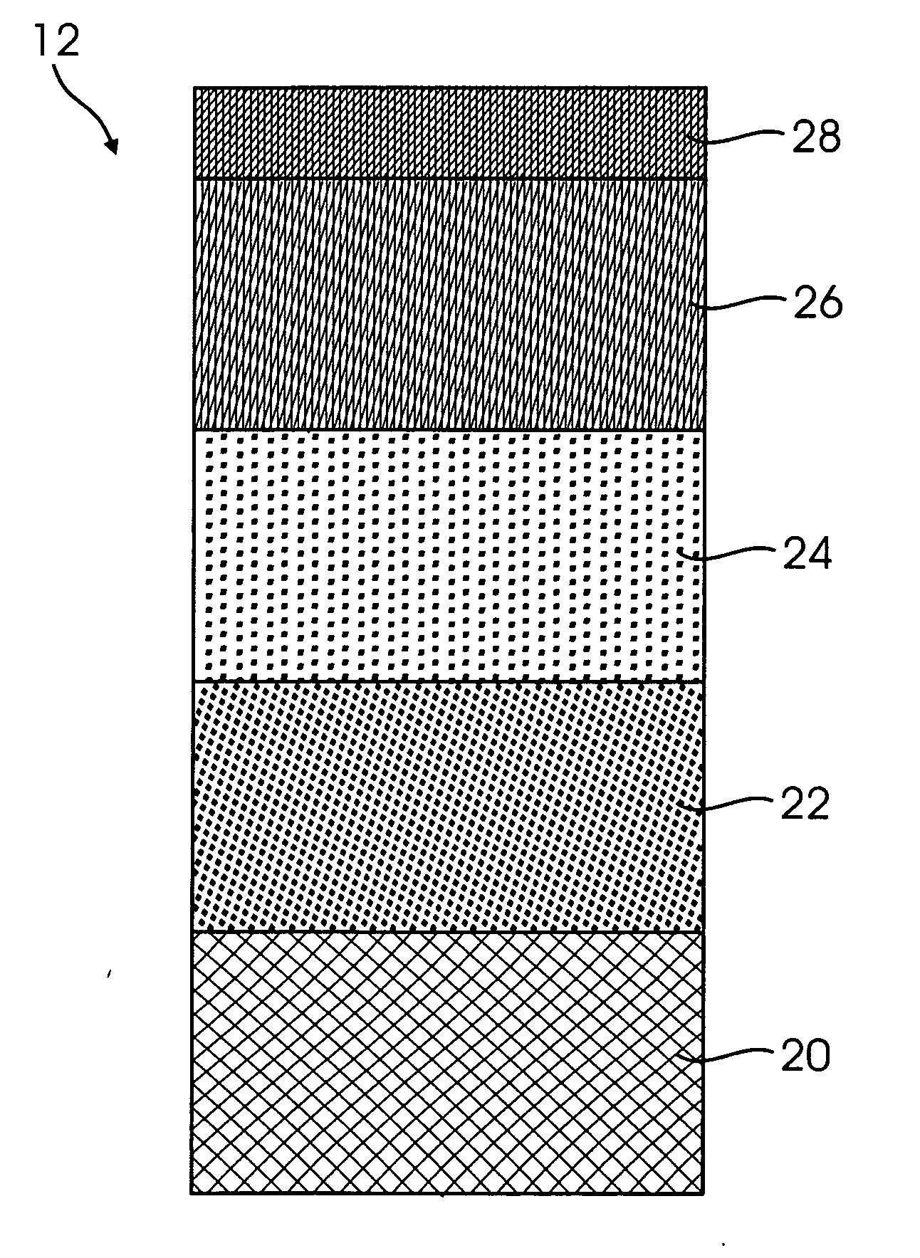
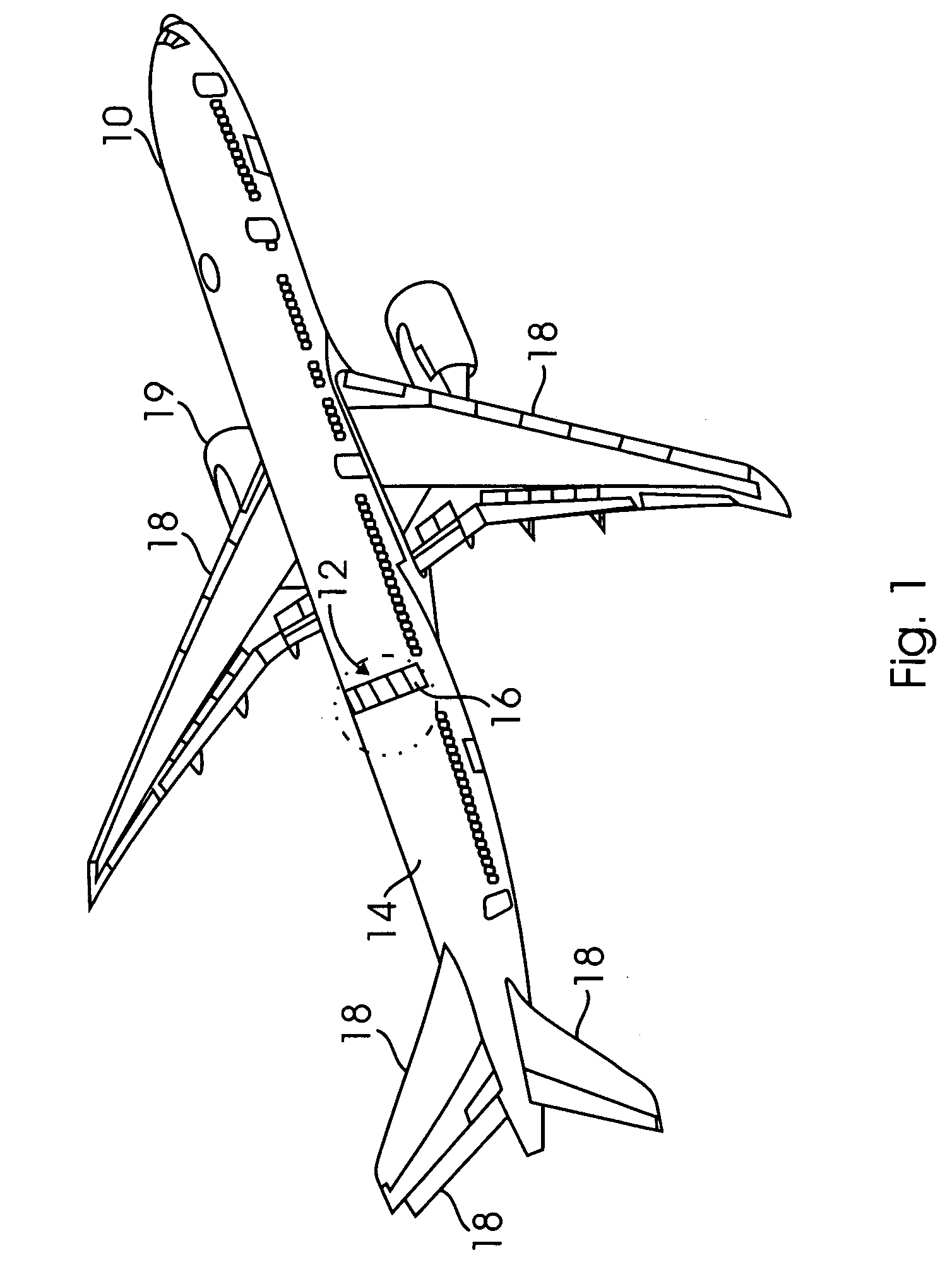
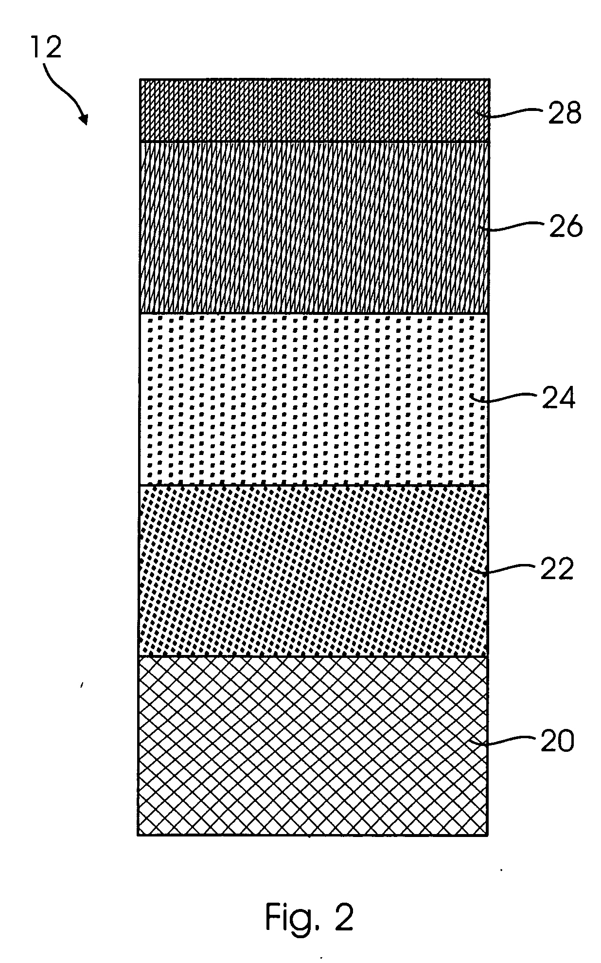
A method of forming an exterior surface protective structure (12) for an aircraft (10) includes providing a surfacer (26) having a carrier on a metal mesh material (24) and an isolator (22) with resin in the surfacer and the isolator filling holes in the metal mesh to form a surface that may be covered with finishes (28), such as spray applied surfacers, primer(s) and a paint to provide a more robust structure that resists corrosion and prevents substrate microcracking, while providing rain erosion resistance, environmental durability, structural performance, and lightning protection in a lighter weight and less costly material.
Description
Login to View More Claims
Login to View More Application Information
Patent Timeline
 OwnerTHE BOEING CO