Weight lifting simulator apparatus

a simulator and weight technology, applied in the field of weight lifting simulator apparatus, can solve the problems of requiring external power sources, noisy, and no control of dynamic inertia of these apparatuses, and achieve the effects of simple configuration manipulation, increased dynamic inertia effect, and compact design

Active Publication Date: 2007-06-21
KOLOMEIR
View PDF21 Cites 48 Cited by
  • Summary
  • Abstract
  • Description
  • Claims
  • Application Information

AI Technical Summary

Benefits of technology

[0006] An advantage of the present invention is that the weight lifting simulator apparatus includes a typically controllable dynamic inertial effect simulation of weight displacement in addition to a static inertial effect; the dynamic inertia effect being increased, this increase being dependent on the speed of the activation movement of the apparatus. Typically, the apparatus enables, through a relatively simple mechanism, simulation of weight lifting with a control of the amount of dynamic inertial effect, from constant force with negligible inertial effect all along its extension path to a more real inertial effect feel of the weight as found in conventional weight lifting apparatuses using real physical weights.
[0007] An advantage of the present invention is that the apparatus is of compact design and construction using elastic or pneumatic technology, and preferably compressible elastic fluid technology for the simulation of weight resistance without the use of active compressor.
[0008] Another advantage of the present invention is that the apparatus allows a ready control and modulation of the weight resistance and/or the dynamic weight inertia effect simulation by simple manipulation of the configuration.
[0009] According to the present invention there is provided a weight lifting simulator apparatus comprising a frame, a guideway pivotally mounted o

Problems solved by technology

In most prior art apparatus control of the resistance level is effected by the use of a simple valve in conjunction with an air compressor which is expensive, cumbersome, noisy and require external power source.
None of these apparatuses includes a c

Method used


Image

  • Weight lifting simulator apparatus
  • Weight lifting simulator apparatus
  • Weight lifting simulator apparatus

Examples


Embodiment Construction

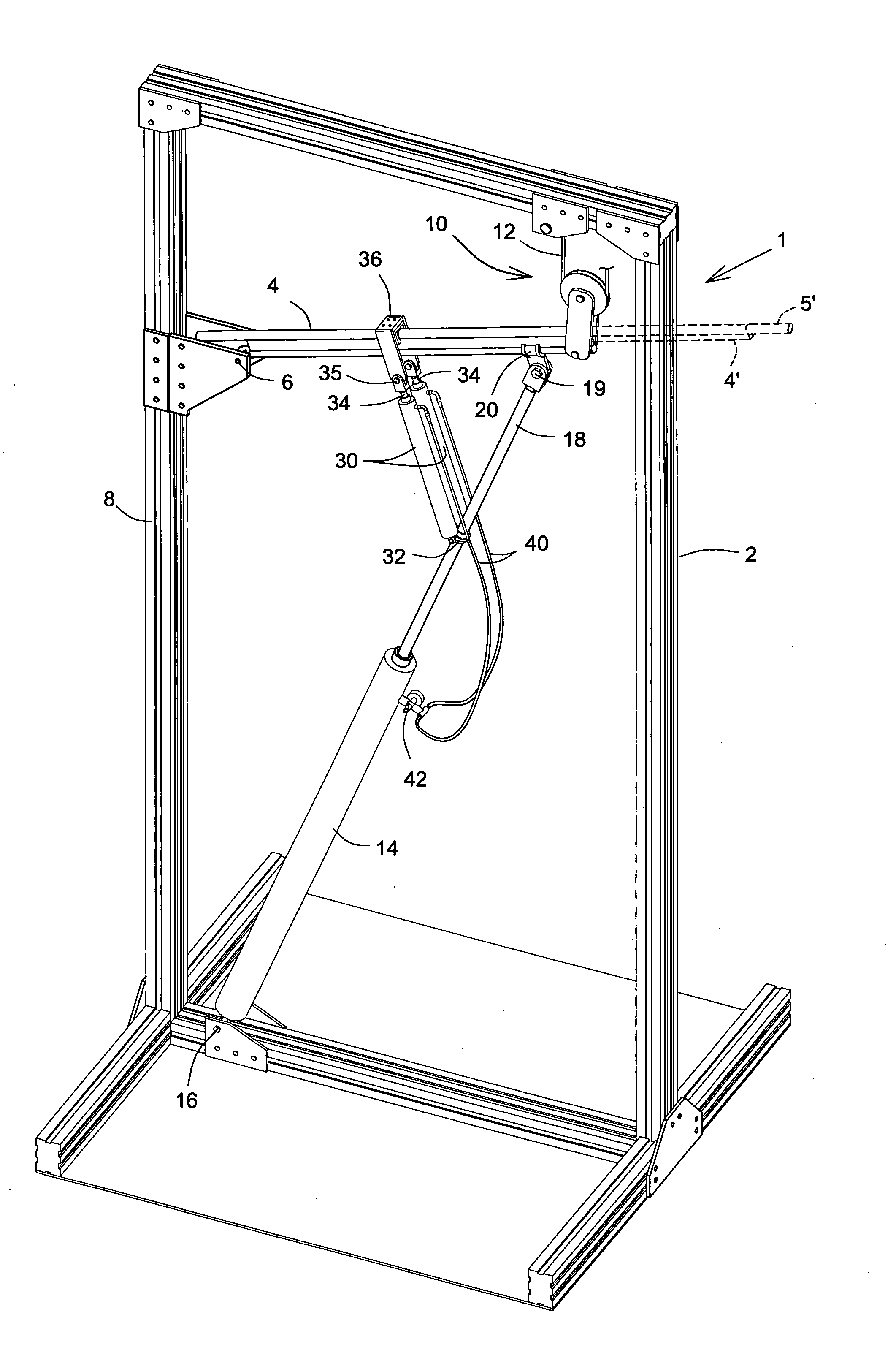
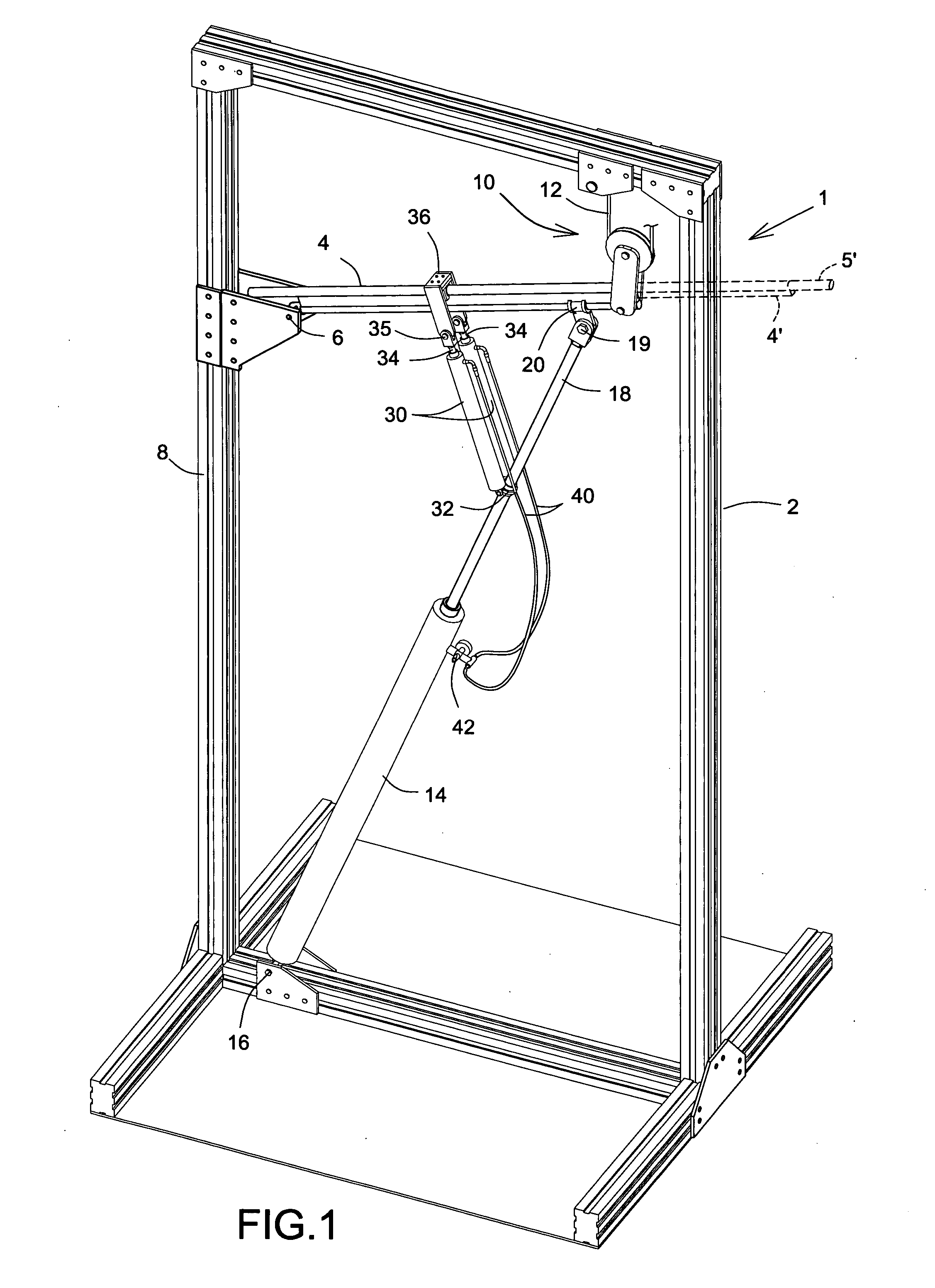
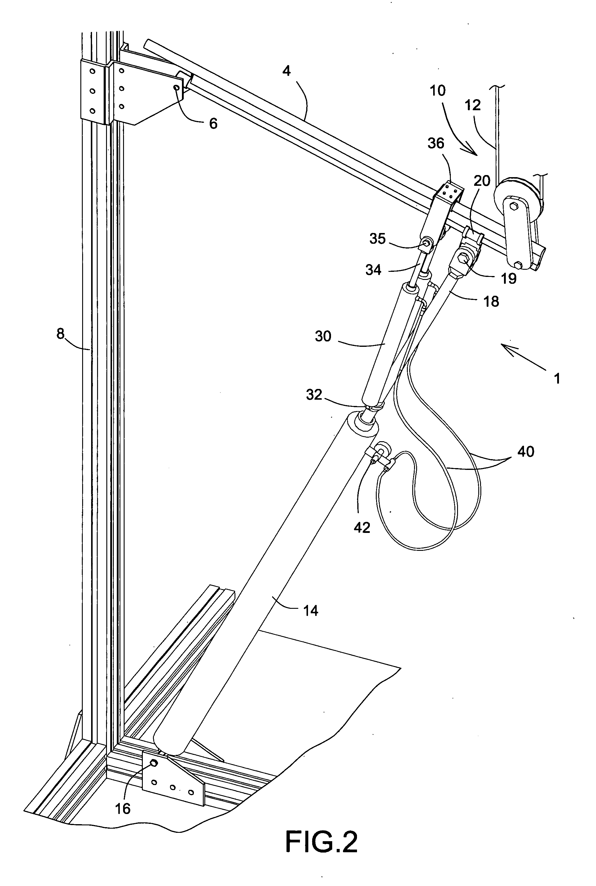
[0044] With reference to the annexed drawings the preferred embodiments of a weight lifting simulator apparatus according to the present invention will be herein described for indicative purpose and by no means as of limitation. Although the following description describes the use of primary and secondary pneumatic cylinders, any elastic behavior load resistant members, such as elastic springs or the like, could be considered without departing from the scope of the present invention.

[0045] Referring first to FIGS. 1 to 4 there is shown a generally rectangular frame 2 of a weight lifting simulator apparatus 1, a guideway 4, or arm, being pivotally mounted thereon at pivot 6 on a side limb 8 thereof for rotation about a pivot axis between two limit angular positions (one position limiting stopper being the piston rod 18 fully retracted inside the cylinder 14 as detailed hereinbelow and shown in FIGS. 2, 4, 7, 8 and 9, the other being shown in FIG. 9 in dotted lines). The free end of ...


PUM


Abstract

Weight lifting simulator apparatus includes a primary pneumatic cylinder providing the principal resistance for simulating weight lifting exercise with at least one secondary cylinder in free fluid interconnection with the primary cylinder whereby constant and balanced loading is achieved, with provisions for dynamic simulation of weight inertia effect, and control thereof, as in lifting a real weight. The primary and the secondary cylinders are associated with a guideway, the primary cylinder being fixed to the guideway and the secondary cylinder being slidable relative to the guideway and pivotable relative to the piston rod of the primary cylinder. Variation of the securement position of the primary cylinder on the guideway is available and valving is provided in the fluid interconnection.

Description

CROSS REFERENCE TO RELATED APPLICATIONS [0001] The present application is a continuation-in-part (C.I.P.) of application Ser. No. 11 / 434,169, filed on May 16, 2006, that is a continuation-in-part (C.I.P.) of application Ser. No. 11 / 293,374, filed on Dec. 5, 2005.FIELD OF THE INVENTION [0002] The present invention relates to weight lifting simulator apparatus for exercise or therapeutic use. BACKGROUND OF THE INVENTION [0003] Weight lifting simulator apparatus of conventional form includes the provision of weights giving a resistance loading, which may be varied by selection, for a user who activates the apparatus using a gripping handle operating on a cable and pulley or lever mechanism. It is also known to employ such simulator apparatus that includes either a resistance arrangement on its own, being either elastic, pneumatic or the like, or in combination with weights. Examples of such apparatus are disclosed in US Patent application publication No. US 2003 / 0115955 to Keiser, whic...

Claims


Application Information

Patent Timeline
IPC IPC(8): A63B21/00
CPCA63B21/00072A63B21/0083A63B21/154A63B21/1484A63B21/1492A63B23/03566A63B21/00069A63B21/0087A63B21/4043A63B21/4047
Inventor KOLOMEIR, JOSEPH
Owner KOLOMEIR
Why Eureka
Try Eureka