Monomer recovery by returning column overhead liquid to the reactor

a technology of overhead liquid and monomer, which is applied in the direction of vacuum distillation separation, separation process, chemical/physical/physico-chemical process, etc., can solve the problems of significant challenge, considerable cost savings, and the inability of polymerization processes to employ separate diluents, etc., to achieve the desired improvement of monomer yield, the effect of significant challeng

Inactive Publication Date: 2007-06-21
CHEVRON PHILLIPS CHEMICAL CO LP
View PDF70 Cites 31 Cited by
  • Summary
  • Abstract
  • Description
  • Claims
  • Application Information

AI Technical Summary

Problems solved by technology

However, some polymerization processes may not employ a separate diluent, such as in the case of selected examples of polypropylene production where the propylene monomer itself acts as the diluent.
Indeed, olefin monomer is typically the largest cost in producing polyolefins, with small incremental improvements in monomer yield resulting in considerable cost savings.
Such desired improvements in monomer yield, however, are a significant challenge in the polyolefin industry.
The polyolefin industry's struggles to increase monomer yield further are due, in part, to the difficulty of separating small amounts of monomer entrained in light component streams and vent/purge streams throughout the polyolefin process, such as in the diluent/monomer recovery and fractionation sections of the polyolefin plant.
Separation of entrained monomer from these light streams is typically not feasible for a variety of reasons.
As appreciated by those of ordinary skill in the art, theoretical limitations, such as azeotropes, pinch points, et

Method used


Image

  • Monomer recovery by returning column overhead liquid to the reactor
  • Monomer recovery by returning column overhead liquid to the reactor
  • Monomer recovery by returning column overhead liquid to the reactor

Examples


Embodiment Construction

[0022] One or more specific embodiments of the present invention will be described below. In an effort to provide a concise description of these embodiments, not all features of an actual implementation are described in the specification. It should be appreciated that in the development of any such actual implementation, as in any engineering or design project, numerous implementation-specific decisions must be made to achieve the developers' specific goals, such as compliance with system-related and business-related constraints, which may vary from one implementation to another. Moreover, it should be appreciated that such a development effort might be complex and time consuming, but would nevertheless be a routine undertaking of design, fabrication, and manufacture for those of ordinary skill having the benefit of this disclosure.

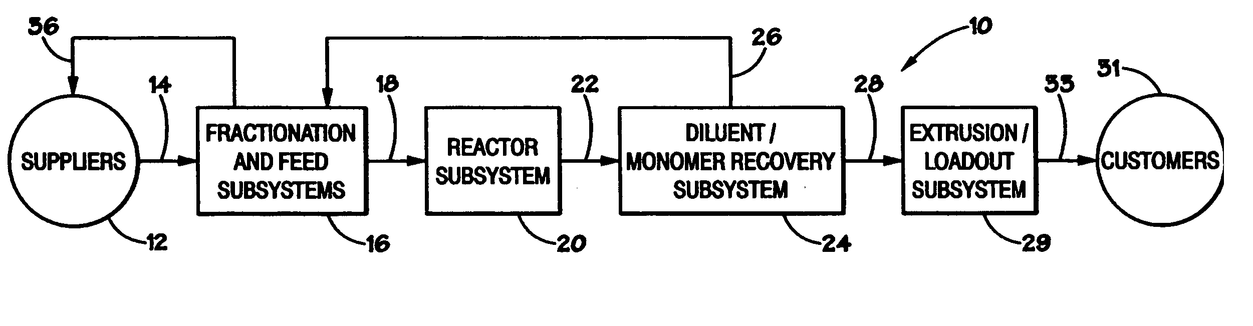
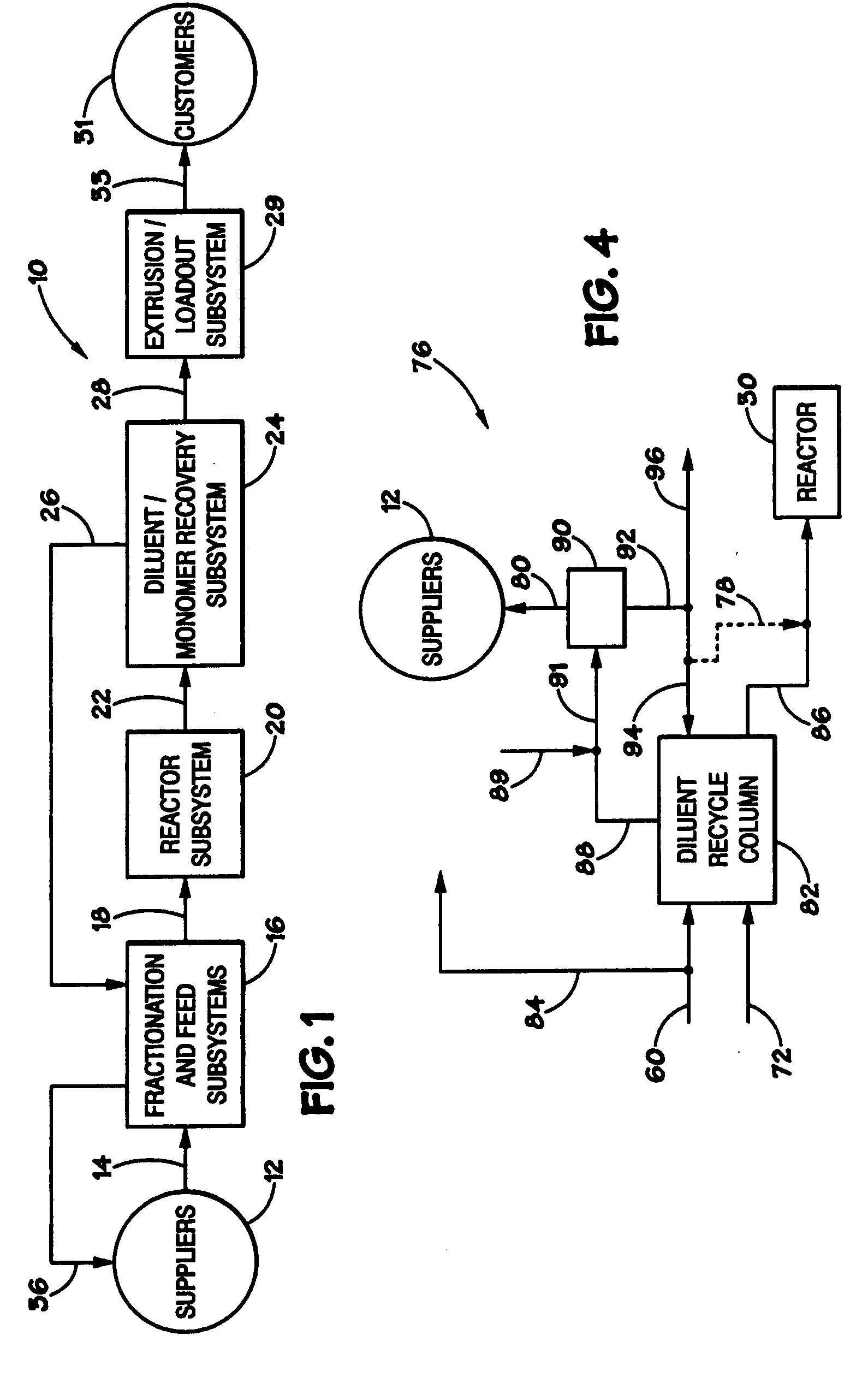
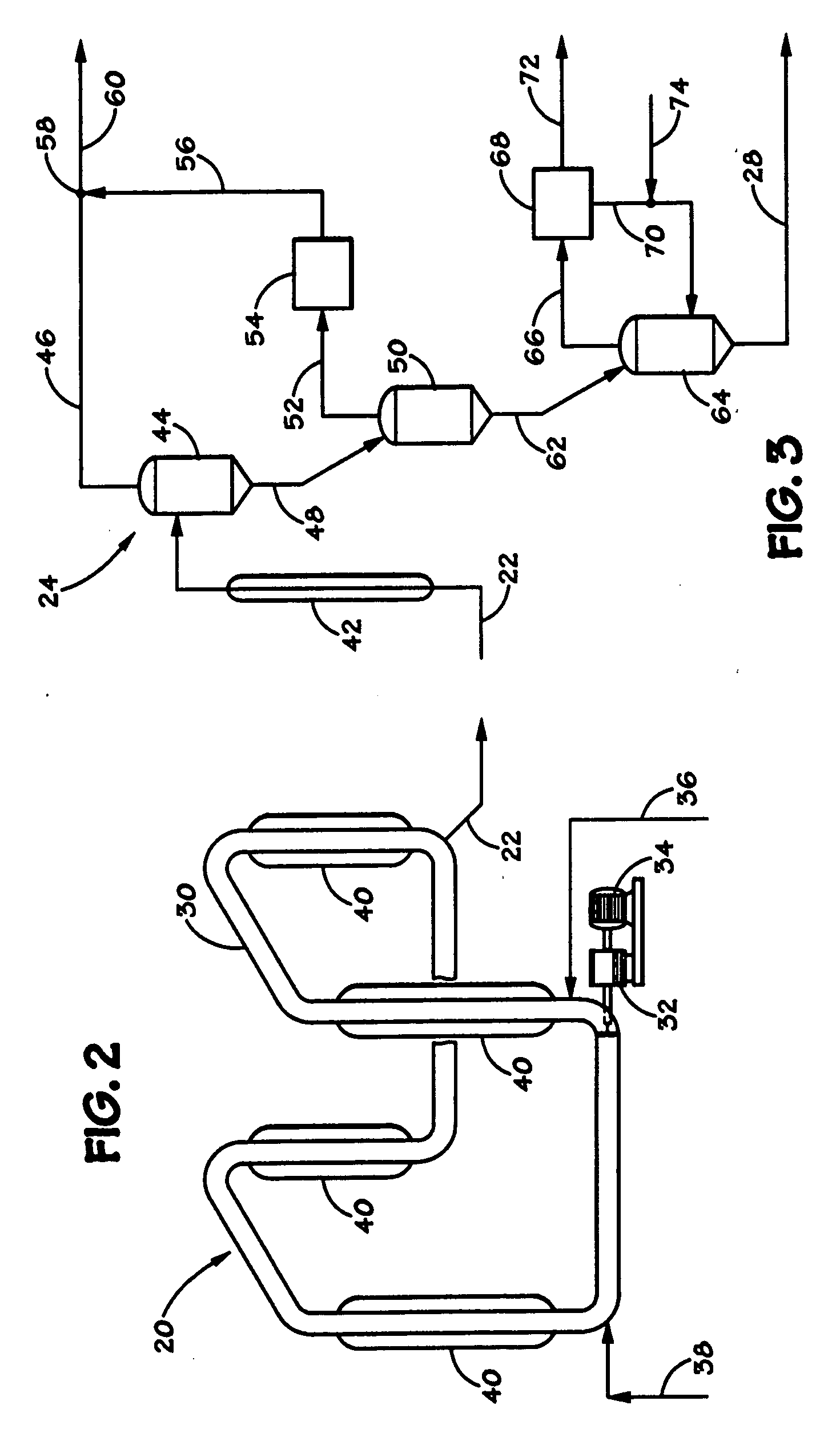
[0023] The present techniques relate to increased recovery of olefin monomer in a polyolefin manufacturing system. The techniques may address the polyol...


PUM

PropertyMeasurementUnit
Temperatureaaaaaaaaaa
Pressureaaaaaaaaaa
Pressureaaaaaaaaaa

Abstract

A polyolefin production system, comprising a polymerization reactor (such as a polyethylene loop slurry reactor) and a fractionation system that receives reactor effluent processed in a diluent/monomer recovery system for recycle to the reactor and to suppliers. A conduit diverts a portion of a reflux flow comprising monomer, such as ethylene, from within the fractionation system to the polymerization reactor, providing for less venting of monomer, such as ethylene, to the supplier. Accordingly, monomer yield is advantageously increased, as the monomer returned to the reactor displaces monomer feedstock to the reactor. The reflux flow may originate from a condensed overhead lights from a diluent recycle column disposed in the fractionation subsystem. The diluent recycle column may receive a stream comprising diluent and monomer as feed from the diluent/monomer recovery subsystem, and may receive the non-diverted portion of the reflux flow as reflux.

Description

BACKGROUND OF THE INVENTION [0001] 1. Field of the Invention [0002] The present invention relates generally to polyolefin production and, more specifically, to increasing recovery of unreacted olefin monomer discharged from a polyolefin reactor. [0003] 2. Description of the Related Art [0004] This section is intended to introduce the reader to aspects of art that may be related to aspects of the present invention, which are described and / or claimed below. This discussion is believed to be helpful in providing the reader with background information to facilitate a better understanding of the various aspects of the present invention. Accordingly, it should be understood that these statements are to be read in this light, and not as admissions of prior art. [0005] As chemical and petrochemical technologies have advanced, the products of these technologies have become increasingly prevalent in society. In particular, as techniques for bonding simple molecular building blocks into longer...

Claims


Application Information

Patent Timeline
IPC IPC(8): C08F2/00
CPCB01J19/1837B01J2208/00274B01J2208/00761B01J2219/00006C08F6/003C08L23/00Y10S526/92
Inventor TAIT, JOHN H.MURPHY, ROBERT S.WATTS, MICHAEL A.GUPTA, ANURAG
Owner CHEVRON PHILLIPS CHEMICAL CO LP
Why Eureka
Try Eureka