[0010]The present invention is made in view of the aforementioned circumstances. It is therefore a principal object of the present invention to provide an error-correction assistance
system capable of readily identifying an error occurrence site in a drive mechanism in a workpiece processing process or a workpiece transporting process, and efficiently correcting an error occurring at the error occurrence site.
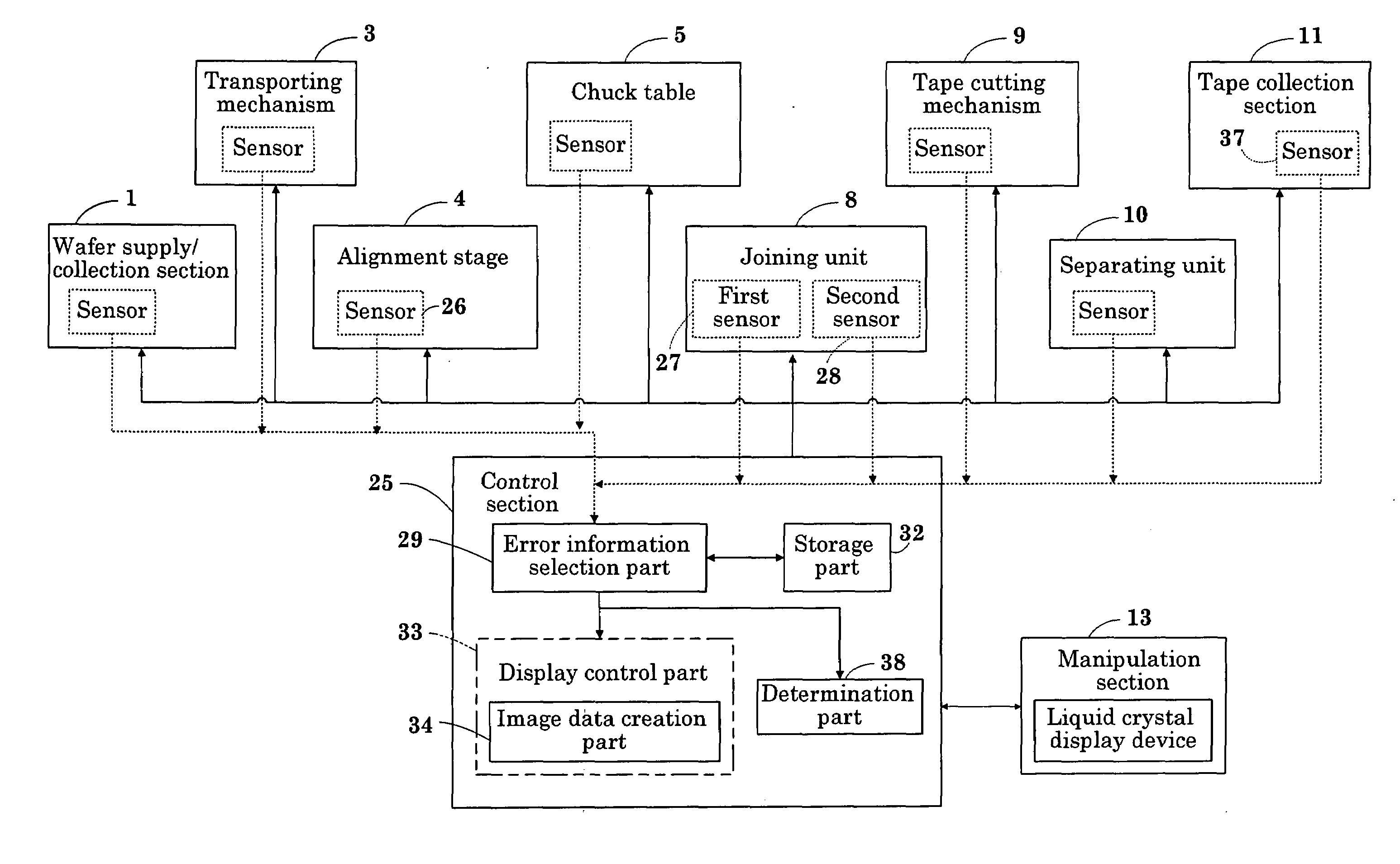
[0013]In the error-correction assistance system according to the present invention, the detection means detects an error occurring at each drive mechanism, and the error information selection means reads out details of the error and image data of an error occurrence site from the storage means based on a detection
signal transmitted from the detection means. Then, the display means displays the details of the error and an image of the drive mechanism as the error information thus read out. Accordingly, it is possible to readily identify an error occurrence site based on contents displayed on the display means. That is, it is possible to readily identify an error occurrence site even when an operator is lacking in skills. Therefore, it is possible to perform error correction in a short time.
[0014]In addition, upon manipulating the actuation status check means after completion of error correction in an error occurrence site, an operator can readily check whether or not the site subjected to the error correction is in a normal actuation status while monitoring a screen of the display means. Further, when the actuation status check means checks that the error occurrence site is normally actuated, the first image switch means erases an image representing the details of the error displayed on the display means. That is, error correction is performed on an error occurrence site based on contents displayed on the display means and, then, an error correction status can be readily checked on the screen of the display means.
[0022]With this configuration, when an error occurs at one of drive mechanisms, a second image as character information about details of the error is highlighted in the display means. When an operator manipulates the second image switch means to switch a screen of the display means from the second image to a first image, a position of detection means that detects the error is displayed on an image representing a configuration of a drive mechanism. Thus, it is possible to identify an error occurrence site more readily.
[0023]Further, when the operator manipulates the actuation status check means in a state that the display means displays the second image, the detection means checks whether or not the error occurrence site is actuated normally. Then, there is highlighted a position of detection means of a drive mechanism having an error displayed on the display means in one of a case of a
normal state and a case of an error occurrence state. Accordingly, the operator does not necessarily to visually check an operation of the error occurrence site in a state that the drive mechanism is operated, and can readily check an operation state only by monitoring the display means. That is, the operator performs error correction in accordance with contents displayed on the display means without referring to a manipulation manual and the like. Therefore, it is possible to complete error correction in a short time without erroneous procedure.
[0027]With this configuration, all manipulations for check can be performed in an
image display region of the display means. Thus, unnecessary operations are eliminated, so that processing work efficiency can be improved. In addition, a display mode is highlighted by manipulation of the switch means; therefore, it is possible to check that the display means is operated normally and to readily check whether or not the error occurrence site subjected to error correction is normal.

