Linear actuator

a linear actuator and actuator technology, applied in the direction of mechanical equipment, mechanical energy handling, gears, etc., can solve the problems of inferior operability and inspection of precision, and achieve the effect of enhancing the detection precision of the rotation amount of the shaft, preventing unnecessary rotation of each gear, and excellent operability

Inactive Publication Date: 2007-06-28
MITSUBA CORP
View PDF6 Cites 25 Cited by
  • Summary
  • Abstract
  • Description
  • Claims
  • Application Information

AI Technical Summary

Benefits of technology

[0008] An object of the present invention is to provide a linear actuator in which a position detection apparatus can precisely be assembled with excellent operability.
[0010] According to the present invention, since the aligning operation of origin points between the moving cylinder and the position detection apparatus can be carried out by adjusting the positional relation between the moving cylinder and the position detection apparatus in the housing, it is possible to precisely assemble the position detection apparatus into the linear actuator with excellent operability.
[0011] The position detection apparatus comprises a potentiosensor which converts the rotation amount of the shaft into a voltage value, and the position detection apparatus is movably provided on the housing. With this, the origin point of the moving cylinder and the origin point of the voltage value of the potentiosensor can precisely be matched with each other. Therefore, it is possible to enhance the detection precision of the rotation amount of the shaft of the potentiosensor.
[0012] A driven gear is mounted on a sensor shaft of the potentiosensor, the driven gear is meshed with a pinion which rotates in unison with the shaft, and the potentiosensor can move in an axial direction of the moving cylinder or toward an axis of the moving cylinder. With this, since it is possible to prevent unnecessary rotation of each gear when the driven gear is meshed with the pinion, it is possible to assemble the various members precisely.
[0013] The potentiosensor can slide in the axial direction of the moving cylinder or toward the axis of the moving cylinder. With this, it is possible to mesh the driven gear with the pinion only by sliding the potentiosensor. Therefore, it is possible to easily assemble the potentiosensor to the linear actuator.

Problems solved by technology

At that time, when a potentiosensor whose voltage value is adjusted to a predetermined value is to be assembled, there is an adverse possibility that the driven gear is rotated when the driven gear is meshed with the pinion, and there is a problem that the position precision must be inspected again after the assembling operation and the operability is inferior.

Method used


Image

  • Linear actuator
  • Linear actuator
  • Linear actuator

Examples


Embodiment Construction

[0025] One embodiment of the present invention will be explained with reference to the drawings.

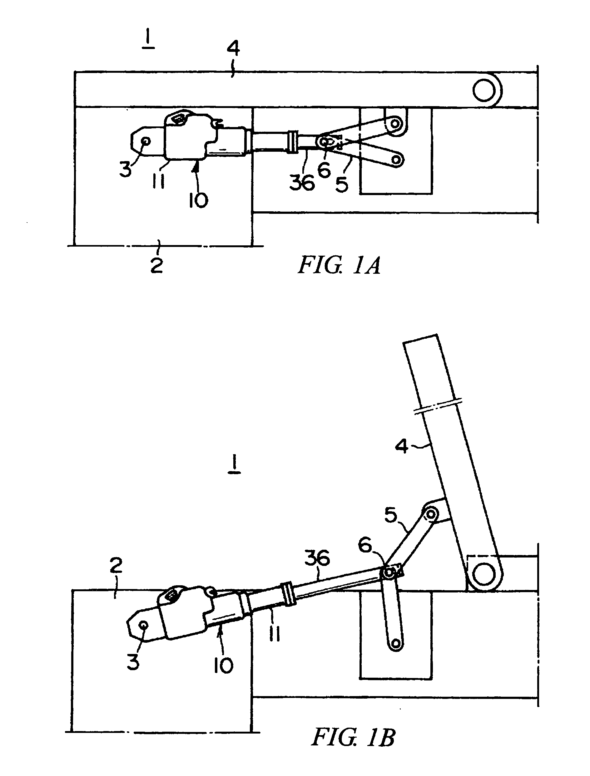
[0026] As shown in FIG. 1, a linear actuator according to the embodiment is for tilting up or lying a bed-plate of a back of a medical / care bed (bed, hereinafter). That is, a housing 11 located on the side of a fixed end of the linear actuator 10 is rotatably supported around a pivot 3 by a frame 2 of the bed 1. A tip end of a moving cylinder 36 located on the side of a free end of the linear actuator 10 is rotatably connected to a link 5 around a pivot 6. The link 5 is for tilting up and lying a bed-plate 4 of the back (bed-plate, hereinafter). In a state in which the moving cylinder 36 of the linear actuator 10 is shrunk, the bed-plate 4 is lying horizontally as shown in FIG. 1A, and if the moving cylinder 36 of the linear actuator 10 is extended, the bed-plate 4 tilts up as shown in FIG. 1B. The bed 1 is not limited to the structure in which the bed-plate 4 tilts up by the extension o...


PUM


Abstract

A shaft 30 in which all of a moving cylinder 36 and a deep groove ball bearing ball bearing 62 are assembled and a reduction gear shaft 73 are assembled to a first shell 12 and then, a potentiosensor 70 is assembled to the first shell 12. A feed coupler is connected to a terminal 50, the driven gear 72 is rotated and adjusted to a predetermined sensor voltage value. The potentiosensor 70 is allowed to slide toward a worm wheel 59, and a large-diameter reduction gear 74 is meshed with a pinion 76.

Description

CROSS-REFERENCE TO RELATED APPLICATIONS [0001] This application is entitled to the benefit of and incorporates by reference essential subject matter disclosed in International Patent Application No. PCT / JP2004 / 019345 filed on Dec. 24, 2004 and Japanese Patent Application No. 2003-428069 filed on Dec. 24, 2003.TECHNICAL FIELD [0002] The present invention relates to a linear actuator, and particularly to an electric feed screw type linear actuator which is for example effectively utilized for vertically moving a bed-plate of a medical / care bed or inclining the bed-plate of a back or knee. BACKGROUND ART [0003] In a medical / care bed, to reduce burden of patient concerning food and sleep, a bed-plate of the bed is vertically moved or the bed-plate of the back or knee is inclined by an electric feed screw type linear actuator. [0004] There is a conventional linear actuator of this kind comprising a shaft having a male thread portion, a worm gear speed reducer which reduces the rotation o...

Claims


Application Information

Patent Timeline
Patent Type & Authority Applications(United States)
IPC IPC(8): F16H27/02F16H29/02F16H25/20H02K7/06H02K11/00
CPCF16H25/2015Y10T74/18576H02K11/00H02K7/06
Inventor INOUE, MASAKIHIRUMA, HIROSHI
Owner MITSUBA CORP
Why Eureka
Try Eureka