Control method for acceleration and braking a vehicle

Inactive Publication Date: 2007-06-28
GOTTHARDT KLAUS JURGEN +2
7 Cites 0 Cited by

AI-Extracted Technical Summary

Problems solved by technology

For safety reasons it is, however, not desired to set the drive to a predetermined optimum ...

Benefits of technology

[0047] The small size is advantageous. The play can be minimized via a tension roller. An electric contact, possibly r...

Abstract

A control device for driving and braking a vehicle, preferably a rail vehicle, comprises a first (1) and a second (2) linearly movable operating lever which are disposed next to each other and can be coupled to each other.

Application Domain

Controlling membersMechanical apparatus +5

Technology Topic

Automotive engineeringAcceleration Unit

Image

  • Control method for acceleration and braking a vehicle
  • Control method for acceleration and braking a vehicle
  • Control method for acceleration and braking a vehicle

Examples

  • Experimental program(1)

Example

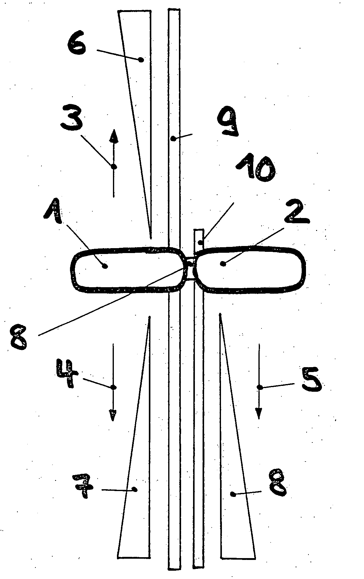
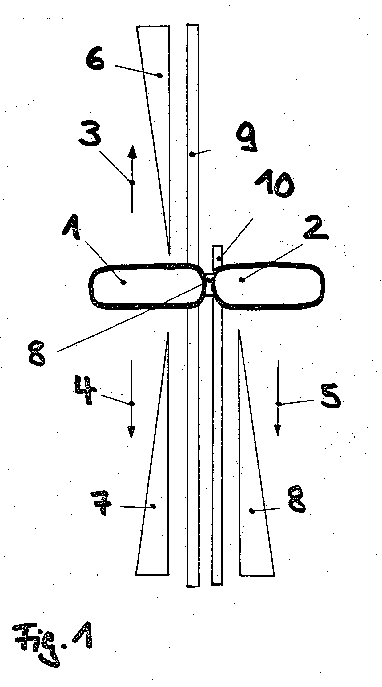
[0052]FIG. 1 shows the zero position of two operating levers 1 and 2 which are disposed in the driver's cab of a rail vehicle (locomotive) at the driver's table to move and brake the rail vehicle. A linear motion of the operating lever 1 in the direction of arrow 3 sets the tractive power, i.e. acceleration of the rail vehicle. A linear motion of the operating lever 1 in the direction of arrow 4 sets an electric brake for generating a braking effect on an electro-dynamic basis. A linear motion of the operating lever 2 in the direction of arrow 5 generates a braking effect by means of an indirectly acting compressed air brake. The increase of the set tractive power and the braking forces on the basis of the zero position, is indicated by the bars 6 to 7. Rails 9 and 10 for the operating levers 1 and 2 have locking points for setting predetermined tractive and braking forces. The operating lever 1 is provided with a so-called SiFa key and the operating lever 2 has a locomotive trigger key. The operating levers 1 and 2 have a coupling 8. The SiFa (safety travelling switch) brakes the train or the locomotive when the driver is not able to respond to prevent any danger to other trains. The basic principle of SiFa is very simple: The locomotive driver must actuate a key every 30 seconds (which varies depending on the vehicle or SiFa type) to communicate to the locomotive that he/she is conscious.
[0053]FIG. 2 shows preselection of a value for the tractive power by means of the operating lever 1 when the SiFa key is actuated. The operating levers 1 and 2 are decoupled.
[0054]FIG. 3 shows coupled braking by means of both operating levers 1 and 2.
[0055] In addition to coupled braking, individual braking is also possible which is shown in FIG. 4 wherein the operating levers 1 and 2 are decoupled (see coupling means 8a and 8b).
[0056]FIG. 5 shows a sole brake setting of the indirectly acting compressed air brake via the operating lever 2 which is decoupled from the operating lever 1. The operating lever 1 is in the zero position (no preselection of tractive power value).
[0057]FIG. 6 shows that the operating levers 1 and 2 also permit a so-called filling stroke. Actuation of a driver braking valve by means of the operating lever 2 energizes a magnet valve and compressed air is additionally released producing a larger cross-sectional opening in the connection between main compressed air line and main braking line and the pressure rises as long as it is actuated. After termination of the filling stroke, the pressure is again decreased.
[0058] In accordance with FIG. 7, the electric brake can be actuated alone (operating lever 1).
[0059]FIG. 8 shows decoupled braking with electric brake and compressed air brake through actuation of both decoupled operating levers 1 and 2.
[0060] Also driving (operating lever 1) against the indirectly acting compressed air brake (operating lever 2) is feasible (see FIG. 9).
[0061] When the operating levers 1 and 2 are decoupled (driving) rapid braking is possible as shown by the lever positions of FIG. 10.
List of Reference Numerals
[0062] 1 operating lever [0063] 2 operating lever [0064] 3 direction of arrow [0065] 4 direction of arrow [0066] 5 direction of arrow [0067] 6 bar [0068] 7 bar [0069] 8 bar [0070] 9 rail [0071] 10 rail

PUM

no PUM

Description & Claims & Application Information

We can also present the details of the Description, Claims and Application information to help users get a comprehensive understanding of the technical details of the patent, such as background art, summary of invention, brief description of drawings, description of embodiments, and other original content. On the other hand, users can also determine the specific scope of protection of the technology through the list of claims; as well as understand the changes in the life cycle of the technology with the presentation of the patent timeline. Login to view more.

Similar technology patents

Polyaxial bone anchoring device

ActiveUS20130123861A1small sizewide application
Owner:BIEDERMANN TECH GMBH & CO KG

Handheld System for Radar Detection

InactiveUS20080169960A1high reliabilitysmall size
Owner:ROSENBURY ERWIN T

Stream encoder and stream decoder

InactiveUS20070297509A1small sizecost reduction
Owner:PANASONIC CORP

Rotary joint structure of underwater electric manipulator

InactiveCN101045301Acompact structuresmall size
Owner:SHENYANG INST OF AUTOMATION - CHINESE ACAD OF SCI

Classification and recommendation of technical efficacy words

  • small size

Microfabricated elastomeric valve and pump systems

InactiveUS6929030B2high speedsmall size
Owner:CALIFORNIA INST OF TECH

RFID antenna

InactiveUS20060208900A1high efficiencysmall size
Owner:TRANSPACIFIC TECH

Capacitor module, power converter, vehicle-mounted electrical-mechanical system

ActiveUS20070109715A1reduce surge voltagesmall size
Owner:HITACHI ASTEMO LTD

Projection display chip

InactiveUS20100321640A1small sizehigh efficiency
Owner:IND TECH RES INST

Phase-change energy-storage material nanocapsule and preparation method thereof

ActiveCN104449590Asmall sizeImprove stability
Owner:INST OF CHEM MATERIAL CHINA ACADEMY OF ENG PHYSICS
Why Eureka
Try Eureka