Gradient solution sending apparatus

a technology of solution sending and sending apparatus, which is applied in the direction of liquid/fluent solid measurement, process and machine control, peptides, etc., can solve the problems of inability to reuse mixed solutions, waste of mobile phase, and inability to generate pulses or uneven solutions, etc., and achieves high mixing concentration accuracy and reduced pulses

Inactive Publication Date: 2007-06-28
SHIMADZU CORP
View PDF9 Cites 19 Cited by
  • Summary
  • Abstract
  • Description
  • Claims
  • Application Information

AI Technical Summary

Benefits of technology

[0010]In view of the foregoing, an object of the invention is to provide a gradient solution sending apparatus, in which the waste of mixing the mobile phase and discharging it from the split mechanism is eliminated, the pulsation is decreased, and the mixed concentration accuracy is high.

Problems solved by technology

At the same time, a slight fluctuation in solution sending operation has a large influence on the flow rate, so that sometimes pulsation or uneven solution sending is generated.
Therefore, the mixed solution cannot be reused, and the mobile phase is uselessly consumed.
Therefore, the correct flow rate cannot be secured.

Method used


Image

  • Gradient solution sending apparatus
  • Gradient solution sending apparatus
  • Gradient solution sending apparatus

Examples


first embodiment

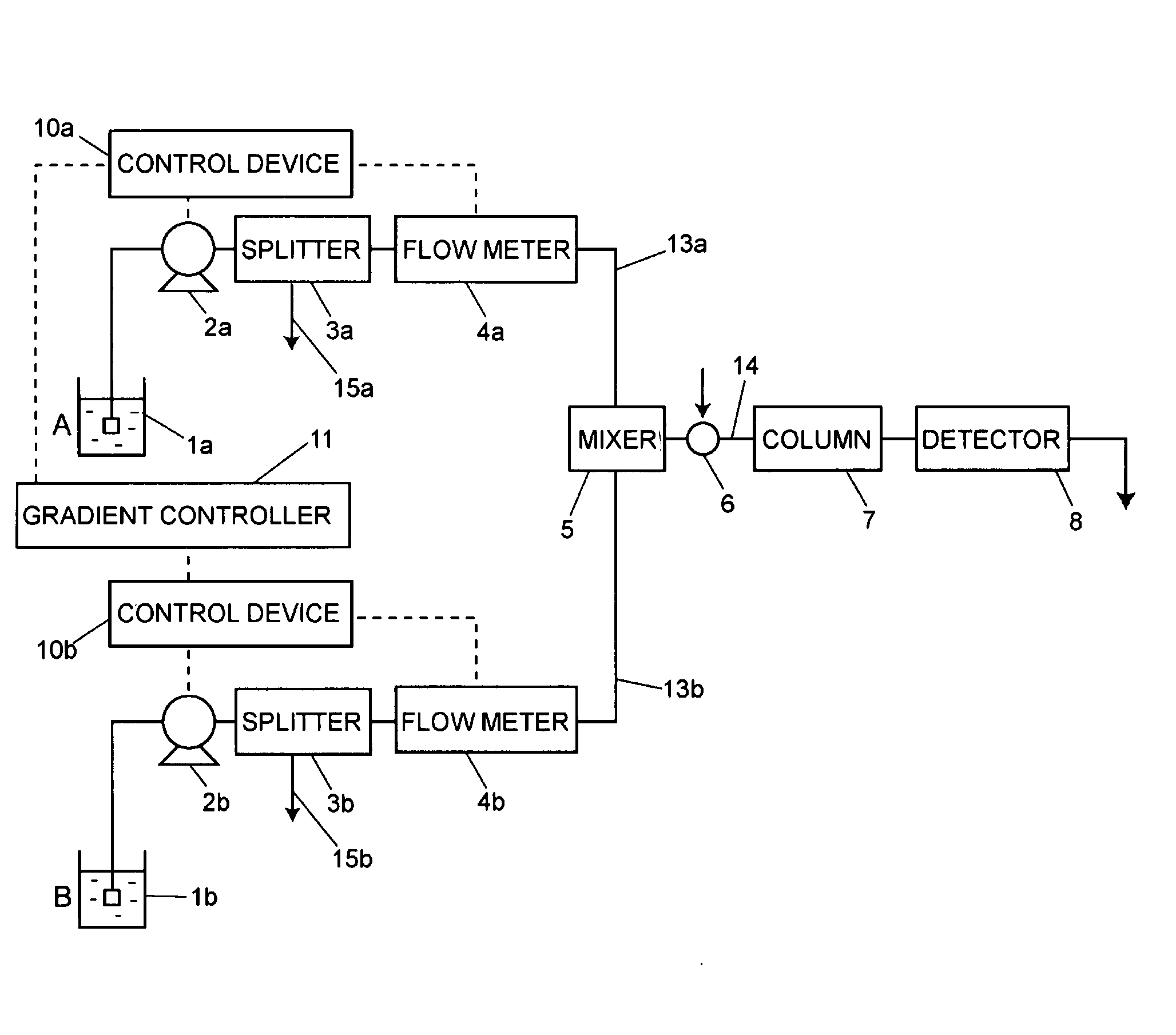
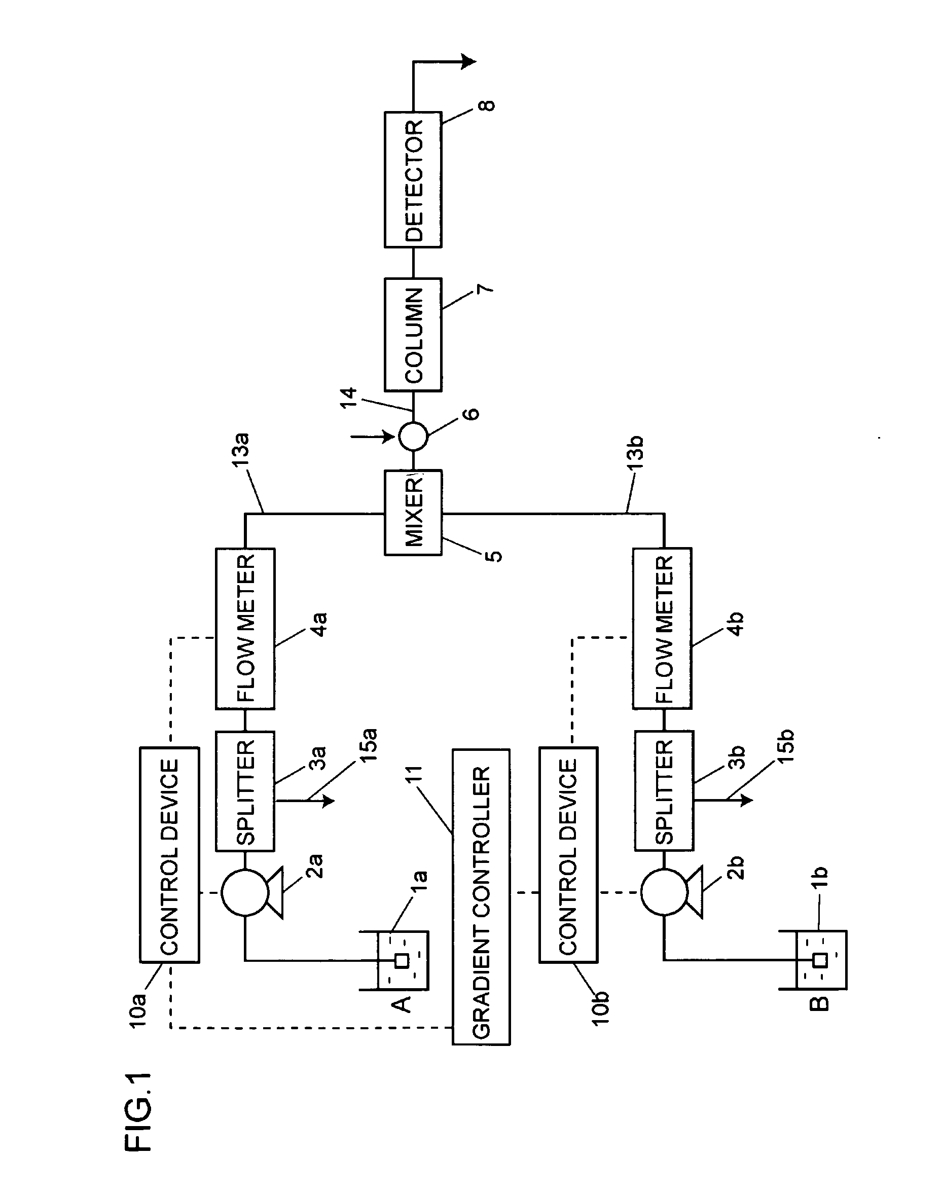
[0034]FIG. 1 is a block diagram showing a flow channel according to a first embodiment of the invention. Solution sending flow channels 13a and 13b send solutions of mobile phases “A” and “B” put in solvent bottles 1a and 1b which are of a mobile phase container. Solution sending pumps 2a and 2b are provided in the solution sending flow channels 13a and 13b, and the solution sending pumps 2a and 2b send the solution of the mobile phases “A” and “B” respectively. Control devices 10a and 10b are connected to the solution sending pumps 2a and 2b, and the control devices 10a and 10b control solution sending mechanisms in the solution sending pumps 2a and 2b according to set flow rates respectively.

[0035]The control devices 10a and 10b are connected to a gradient controller 11, and the gradient controller 11 transmits the set flow rates to the control devices 10a and 10b based on a set gradient program.

[0036]A splitter 3a as a split mechanism for the mobile phase “A” is provided on a dis...

second embodiment

[0051]In operating the gradient solution sending apparatus of the first embodiment shown in FIG. 1, sometimes the mutual interference becomes a problem between the solution sending pumps. That is, the solutions of the mobile phases sent by the two solution sending pumps 2a and 2b interfere with each other through the splitters 3a and 3b.

[0052]FIG. 3 is a block diagram showing a flow channel according to a second embodiment in which improvement is made to suppress the mutual interference. Resistance tubes 12a and 12b are provided as the flow channel resistor between the mixer 5 and the flow meters 4a and 4b of the solution sending flow channels 13a and 13b respectively. The mobile phases split by the splitters 3a and 3b are split by a resistance ratio of the side of the analysis flow channel 14 and the side of the discharge flow channels 15a and 15b respectively. In this case, the discharge flow channels 15a and 15b of the splitters 3a and 3b are connected to the solvent bottles 1a ...


PUM

PropertyMeasurementUnit
flow rateaaaaaaaaaa
pressureaaaaaaaaaa
flow rateaaaaaaaaaa

Abstract

A gradient solution sending apparatus of the present invention includes a plurality of solution sending flow channels, a mixer, a gradient controller in which a solution sending flow rate is set, and a control device which controls a solution sending flow rate of a mobile phase of each solution sending flow channel based on the solution sending flow rate set in the gradient controller. Each solution sending flow channel includes a solution sending pump and a split mechanism. The solution sending pump sends the solution of each mobile phase. The split mechanism delivers a part of the mobile phase passing through the solution sending pump, and the split mechanism discharges the rest of the mobile phase from the solution sending flow channel. A mixer is arranged on downstream sides of the solution sending flow channels, and the mixer mixes the mobile phases sent from the solution sending flow channels and delivers the mixed mobile phase to the analysis flow channel.

Description

BACKGROUND OF THE INVENTION[0001]1. Field of the Invention[0002]The present invention relates to a solution sending apparatus which mixes and sends out at least two solutions, for example, to a mobile-phase gradient solution sending apparatus in liquid chromatography.[0003]2. Description of the Related Art[0004]The solution sending apparatus for micro high-performance liquid chromatography (micro HPLC) and nano high-performance liquid chromatography (nano HPLC) includes a direct type solution sending apparatus and a split type solution sending apparatus. The solution of the mobile phase having a micro flow rate is sucked and sent in the direct type solution sending apparatus. In the split type solution sending apparatus, the solution of the mobile phase having the flow rate ranging from 10 to 1000 μL / min is sucked and split with a split mechanism, and the solution sending is performed only to the mobile phase having the necessary flow rate. For the high-pressure gradient solution se...

Claims


Application Information

Patent Timeline
Patent Type & Authority Applications(United States)
IPC IPC(8): B01D21/26
CPCB01D15/166G01N30/34B01D15/14B01F35/883B01F2101/2204G05D11/035
Inventor KITAGAWA, TAKAEI
Owner SHIMADZU CORP
Why Eureka
Try Eureka