
Intelligent equalizing battery charger having equalization charging circuitry

a charging circuit and intelligent technology, applied in the direction of charging equalization circuit, transportation and packaging, charging circuit for several simultaneous batteries, etc., can solve the problems of reducing the lifespan of the battery in application, increasing the potential difference between the charging battery set and the above-mentioned conventional battery charger circuitry, and avoiding any damage to the battery cells. , accurate control of the charging tim

Inactive Publication Date: 2007-06-28
SINO AMERICAN ELECTRONICS
View PDF2 Cites 47 Cited by
  • Summary
  • Abstract
  • Description
  • Claims
  • Application Information

AI Technical Summary

Benefits of technology

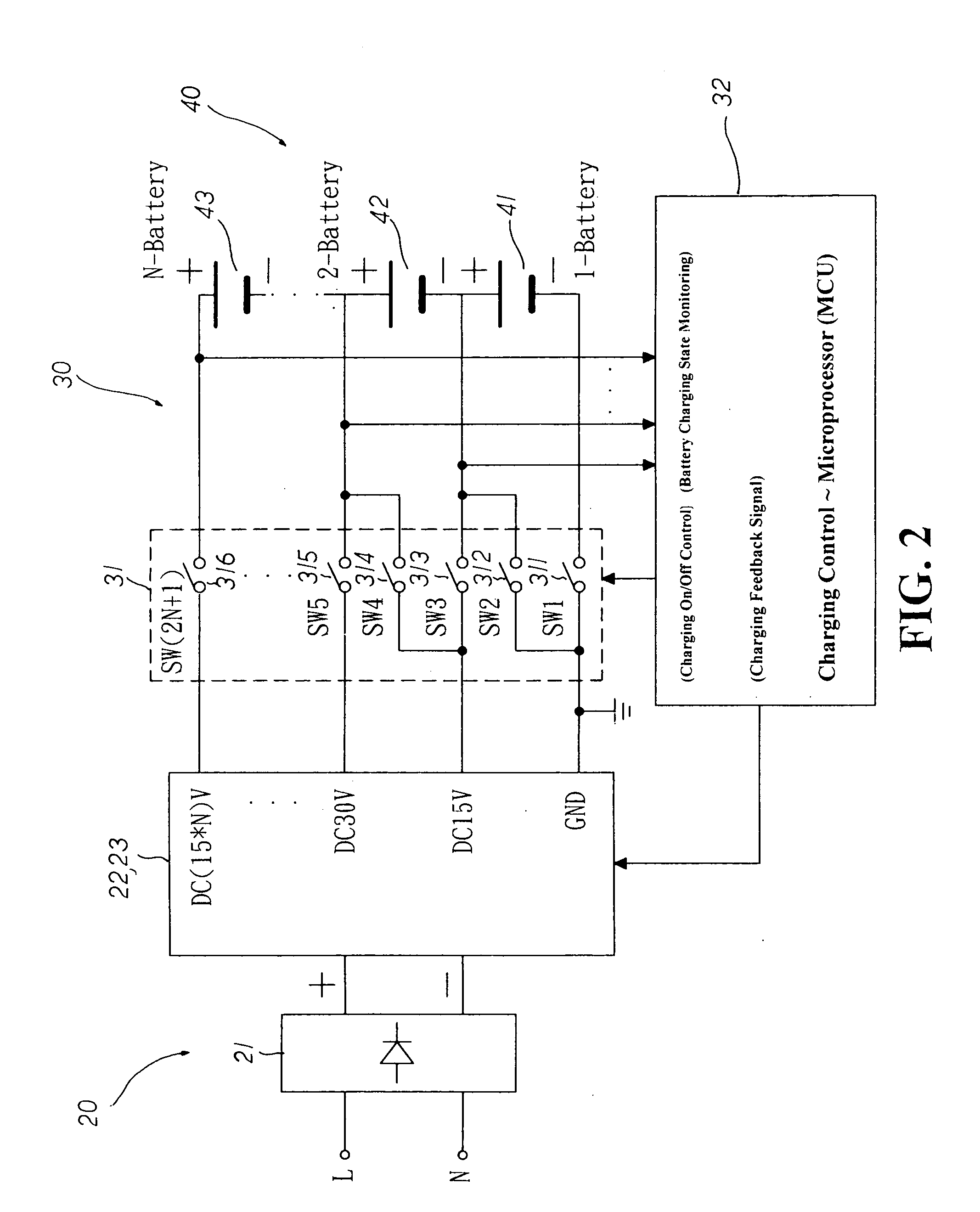
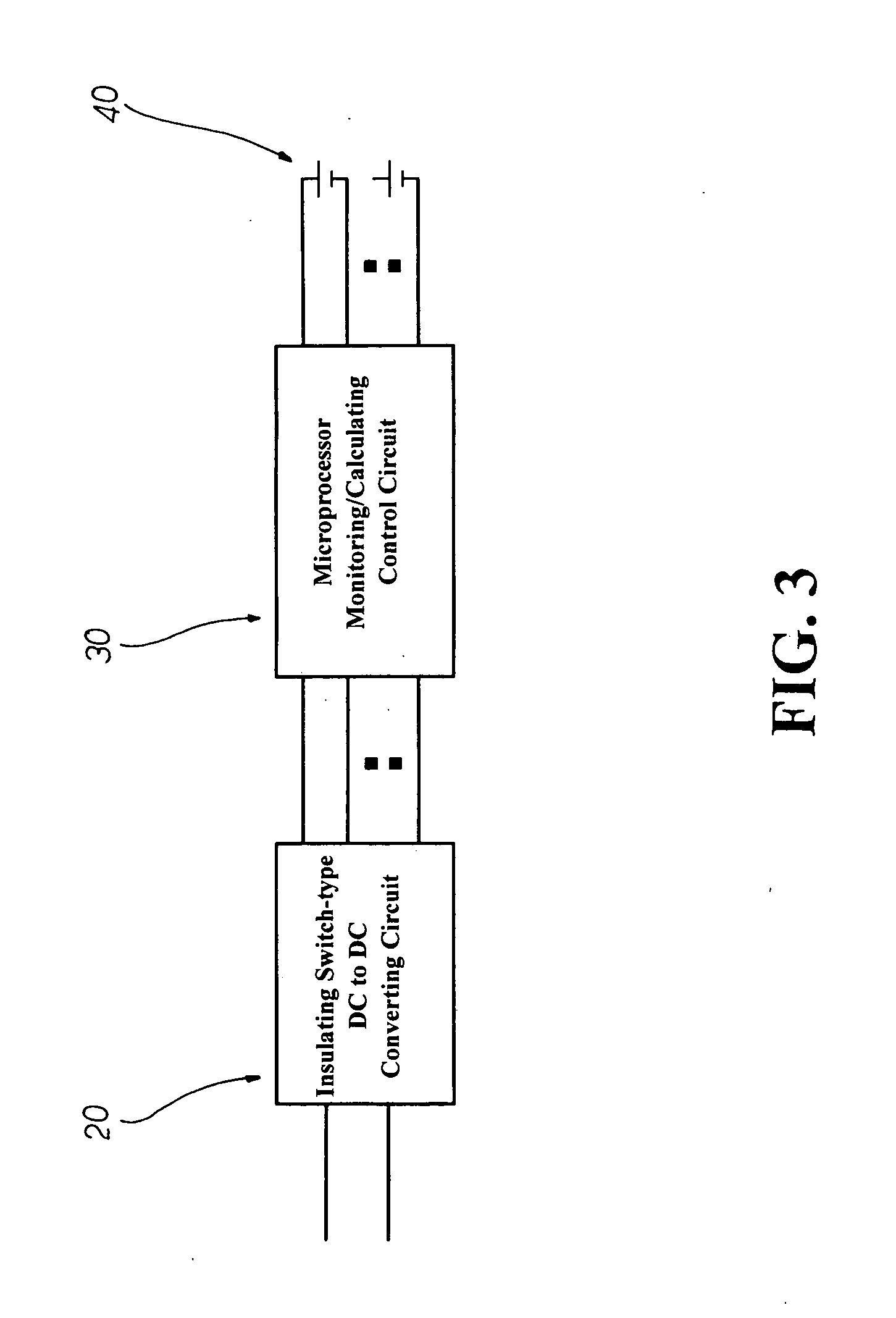
[0004] It is, therefore, the primary purpose of the present invention to provide an intelligent equalizing battery charger having equalization charging circuitry, comprising an insulating switch-type DC to DC converting circuit, a microprocessor monitoring / calculating control circuit, and a charging battery set wherein, after the installment of the battery set for charging, the microprocessor control circuit can monitor the charging voltage and control the charging current during the whole charging process so that each cell of the battery set can be fully charged in equalization to achieve the best charging / discharging state thereby as well as to avoid the increase of the potential difference within the cells thereof, efficiently extending the battery life in application.
[0005] It is, therefore, the second purpose of the present invention to provide an intelligent equalizing battery charger having equalization charging circuitry wherein the microprocessor monitoring / calculating control circuit can provide protection against connection in reverse, avoiding any damages to the battery cells during the charging process due to a wrong-electrode installment thereof. Besides, the microprocessor monitoring / calculating control circuit can also accurately control the charging time and protectively shut off the charging process in case of charging overtime, efficiently achieving the best state of application thereof
[0006] It is, therefore, the third purpose of the present invention to provide an intelligent equalizing battery charger having equalization charging circuitry wherein the microprocessor monitoring / calculating control circuit can control multiple switch elements linked to the charging battery set respectively so that the cells of the battery set can be optionally charged either individually in separation or collectively in string, and can all attain an equalization charging effect thereby, achieving the best state of application thereof.

Problems solved by technology

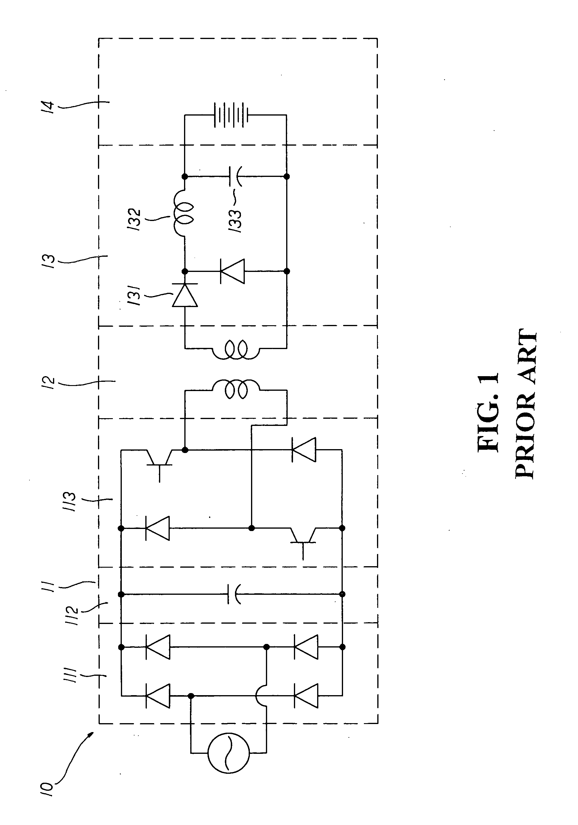
There are some disadvantages to the above-mentioned conventional battery charger circuitry thereof.
As a result, the battery set 14 stringed in series for charging may become overcharged or undercharged in the process, which will cause the increase of the potential difference within the charging battery set 14 and, thus, reduce the lifespan of the battery in application.

Method used


Image

  • Intelligent equalizing battery charger having equalization charging circuitry
  • Intelligent equalizing battery charger having equalization charging circuitry
  • Intelligent equalizing battery charger having equalization charging circuitry

Examples


third embodiment

[0018] Please refer to FIG. 7 showing the power supply switch circuit of the present invention. The power supply convert circuit 61 linked to the primary coil has a switch 612 connected for conduction, permitting the DC power supply to pass through a filtering capacitor 611 before converted via an insulating transformer 62 to feed a rectification converting circuit 63 linked to the secondary coil thereof. Then, the power supply conducted will flow through a rectifying diode 631 and a filtering capacitor 632 to provide the DC power supply necessary for the microprocessor monitoring / calculating control circuit thereof. When the switch 612 linked to the primary coil is blocked from the power supply, the secondary coil will feed the power source to the filtering capacitor 632.

fourth embodiment

[0019] Please refer to FIG. 8 showing the power supply switch circuit of the present invention. A power supply switch circuit 71 linked to the primary coil thereof has a set of switches 713, 714 that can be simultaneously connected for conduction, permitting the DC power supply to pass through a set of filtering capacitor 711, 712 before converted through an insulating transformer 72 to feed a rectification converting circuit 73 linked to the secondary coil thereof. Then, the power supply conducted will flow through a rectifying diode 731, a coupling inductor 733 and a filtering capacitor 734 to provide the DC power supply required for the microprocessor monitoring / calculating control circuit 30 thereof. When the switches 713, 714 linked to the primary coil are blocked from the power supply, the coupling inductor 733 linked to the secondary coil will provide the power to the filtering capacitor 734 via another rectifying diode 732, and the primary coil set will start to release the ...


PUM


Abstract

An intelligent equalizing battery charger having equalization charging circuitry is disclosed, comprising an insulating switch-type DC to DC converting circuit, a microprocessor monitoring / calculating control circuit, and a charging battery set wherein the insulating switch-type DC to DC converting circuit is composed of a power supply switch circuit, an insulating transformer, and a rectification converting circuit. The microprocessor monitoring / calculating control circuit includes multiple switch elements and a charging control microprocessor. Via the aforementioned structure, each individual cell of the charging battery set can be appropriately charged in equalization, which can not only increase the charging / discharging times of the battery set, but also efficiently extend the battery life in application.

Description

BACKGROUND OF THE INVENTION [0001] The present invention is related to an intelligent equalizing battery charger having equalization charging circuitry, comprising an insulating switch-type DC to DC converting circuit, a microprocessor monitoring / calculating control circuit, and a charging battery set wherein the microprocessor monitoring / calculating control circuit, after the installment of the battery cells, can monitor the charging voltage and control the charging current during the whole charging process so that each cell of the battery set can be fully charged in equalization to achieve the best charging / discharging state thereby as well as to avoid the increase of the potential difference within the cells thereof, efficiently extending the battery life in application. [0002] Please refer to FIG. 1. A conventional battery charger includes a charging circuitry 10 composed of a power supply switch circuit 11, a transformer 12, a rectification converting circuit, and a charging ba...

Claims


Application Information

Patent Timeline
Patent Type & Authority Applications(United States)
IPC IPC(8): H02J7/00
CPCH02J7/0019H02M3/33561
Inventor CHIANG, RAYLU, KELVINHUANG, JEFFREY
Owner SINO AMERICAN ELECTRONICS
Learn More