Remote controller

a remote controller and controller technology, applied in the field of remote controllers, can solve the problems that the remote controller has not always been user-friendly to some users, and the display pattern cannot be changed until, so as to achieve the effect of convenient operation for users

Active Publication Date: 2007-06-28
DISPLAY INNOVATIONS INC
View PDF0 Cites 38 Cited by
  • Summary
  • Abstract
  • Description
  • Claims
  • Application Information

AI Technical Summary

Benefits of technology

[0007] The present invention has been made in order to solve the above-described problems. An object is to provide a remote controller which is easy for a user to operate before the learning is carried out.

Problems solved by technology

Accordingly, some of the operation units not used by some users of the remote controller at all may be contained in the remote controller without change, and thus the remote controller has not always been user-friendly to some of the users.
However, in the remote controller disclosed in Japanese Patent Laying-Open No. 09-023487, there has been a problem in that the display patterns cannot be changed until the learning is carried out.

Method used


Image

  • Remote controller
  • Remote controller
  • Remote controller

Examples


first modification

[0082] First Modification

[0083] In the following, a description will be given of a modification of remote controller 100 according to a first modification of the present embodiment. Remote controller 100 according to this modification is different from the remote controller of the above-described embodiment in the point of having a function that the icons displayed on touch panel 310 are changed in accordance with the history of the operations. In this regard, remote controller 100 according to this modification is implemented, for example, using the hardware configuration of remote controller 100 shown in FIG. 3. Accordingly, the following description will be given using the configuration shown in FIG. 3.

[0084]FIG. 15 is a flowchart illustrating a processing procedure executed by control circuit 320 in order to record the history of the operations on remote controller 100.

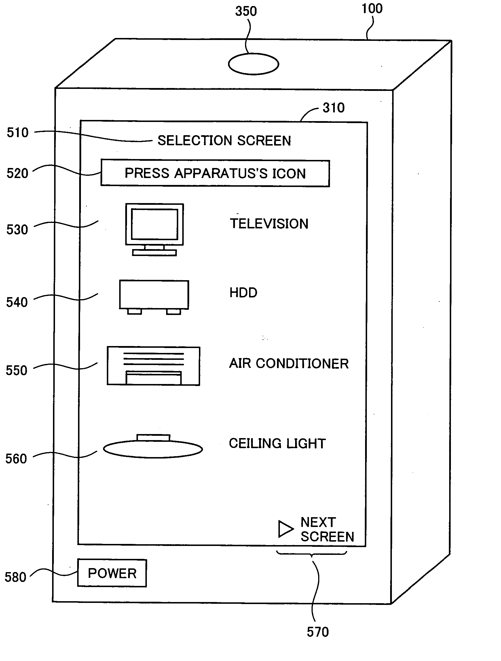
[0085] In step S1510, control circuit 320 outputs a display instruction of the selection screen of the appara...

second modification

[0098] Second Modification

[0099] Next, a description will be given of a second modification of the present embodiment. In the above-described embodiment and the modification thereof, a change of the screens displayed on touch panel 310 has not been described. Thus, a description will be given of a mode of changing the screens for giving instructions to the apparatus.

[0100]FIG. 19 is a diagram illustrating a form of data storage in setting-data memory 344. Setting-data memory 344 includes tables 1910 and 1920 which store data for defining the screens to be displayed on touch panel 310. Table 1910 includes areas 1912 to 1916 for storing data. Table 1920 includes the same areas 1922 to 1926.

[0101] Area 1912 includes the data for identifying, for example, a screen. Area 1914 includes the data for identifying an apparatus. Area 1916 includes an icon for identifying an operation corresponding to that apparatus. This is the same for the data storage in table 1920. In this manner, it is p...


PUM


Abstract

A remote controller allowing a user to change settings is provided. The remote controller includes a touch panel, a control circuit, a screen display memory, a setting data memory, a control data memory, an infrared transmission unit, and a battery. The control circuit includes a screen-display control circuit for displaying an image provided in advance for controlling the operation of a specific apparatus, a pressed-area detection circuit for detecting pressing in the display area of touch panel, an instructed-operation detection circuit for detecting the instruction of an operation, a display-data generation circuit for generating image data for displaying icons in the display area of touch panel, and a control-signal generation circuit for generating a signal for controlling the operation of the apparatus.

Description

BACKGROUND OF THE INVENTION [0001] 1. Field of the Invention [0002] The present invention relates to a remote controller, and more specifically to a remote controller capable of controlling a plurality of apparatuses. [0003] 2. Description of the Background Art [0004] A remote controller generally functions as a device for controlling a specific apparatus. The keys and the other operation units provided with the remote controller accept an operation input for giving a specific instruction to that apparatus. Accordingly, some of the operation units not used by some users of the remote controller at all may be contained in the remote controller without change, and thus the remote controller has not always been user-friendly to some of the users. [0005] For example, Japanese Patent Laying-Open No. 09-023487 has disclosed a remote controller which can identify a user, learn the use frequency of each function for each identified user, and change display patterns in accordance with the le...

Claims


Application Information

Patent Timeline
Patent Type & Authority Applications(United States)
IPC IPC(8): G08C19/00
CPCG08C23/04G08C2201/92
Inventor TAKESHITA, MASAHIRO
Owner DISPLAY INNOVATIONS INC
Why Eureka
Try Eureka