Display device and driving method of display device

a display device and driving method technology, applied in the direction of electric digital data processing, instruments, computing, etc., can solve the problem of inevitability of the display quality degradation of moving images, and achieve the effect of preventing the degradation of display quality and reliably correcting vertical crosstalk

Active Publication Date: 2007-06-28
SONY CORP
View PDF1 Cites 19 Cited by
  • Summary
  • Abstract
  • Description
  • Claims
  • Application Information

AI Technical Summary

Benefits of technology

[0016] Accordingly, it is desirable to provide a liquid crystal display device and a driving method thereof that can prevent degradation in display quality at a time of a moving image due to vertical crosstalk without using a large-scale memory having a capacity to store display data for one screen.
[0017] It is also desirable to provide a display device and a driving method thereof that can more reliably correct vertical crosstalk specific to the field inversion driving system.
[0022] According to yet another embodiment of the present invention, the same correction as that for a still image can be performed for a moving image, and therefore degradation in display quality at a time of a moving image can be prevented. In addition, because correction coefficients corresponding to the respective amounts of crosstalk in different correction areas can be set, vertical crosstalk specific to the field inversion driving system can be corrected more reliably.

Problems solved by technology

On the other hand, the technique in related art described in Patent Document 2 may not correct a moving image properly, and deals with a moving image by turning off a correcting function at the time of a moving image, so that degradation in display quality of a moving image is inevitable.

Method used


Image

  • Display device and driving method of display device
  • Display device and driving method of display device
  • Display device and driving method of display device

Examples


embodiment

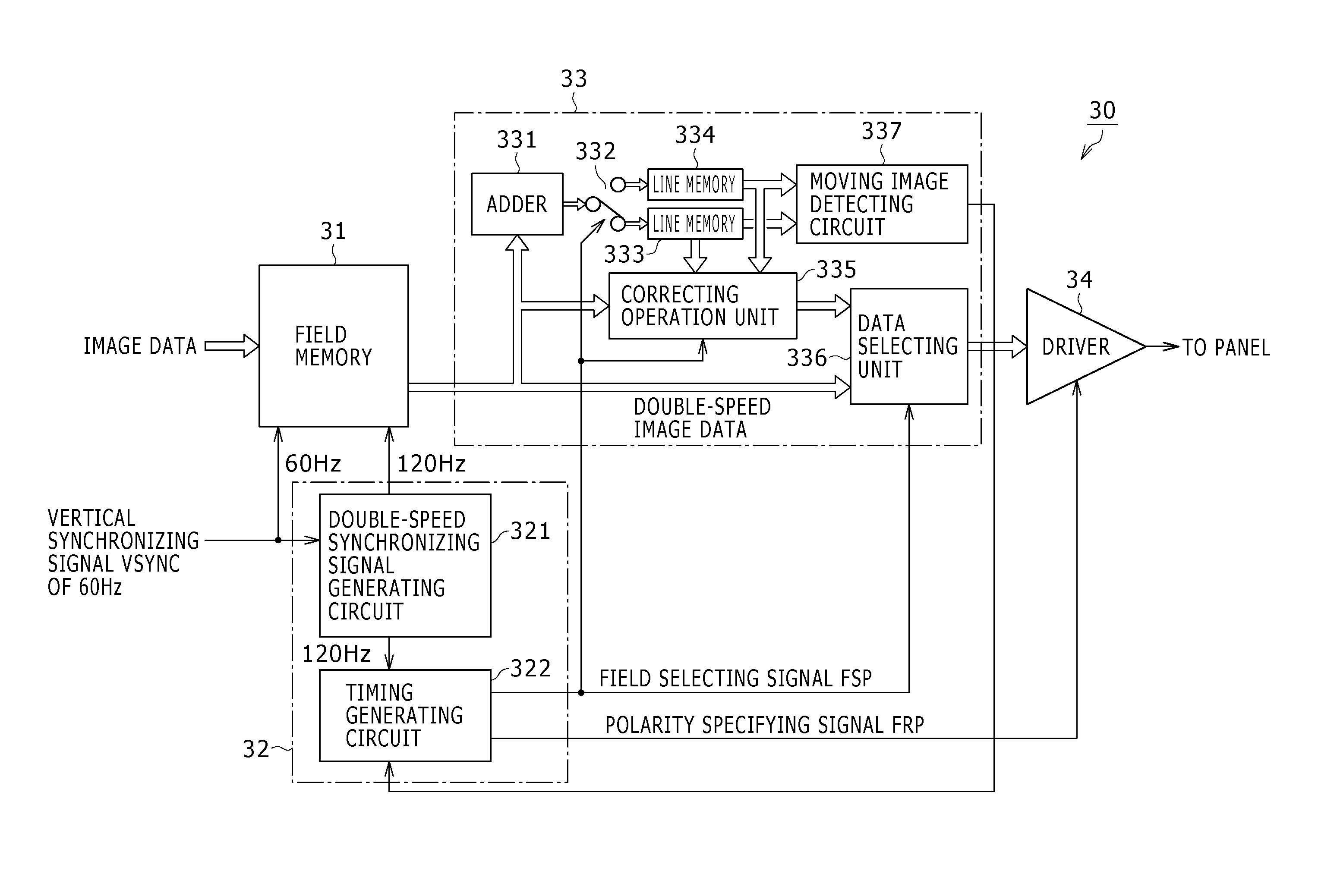
[0062]FIG. 4 is a functional block diagram of the driving circuit 30 including the vertical crosstalk correcting circuit according to one embodiment of the present invention.

[0063] As shown in FIG. 4, the driving circuit 30 includes: a field memory 31 used for double-speed driving; a control circuit 32 for controlling the writing / reading of image data to and from the field memory 31; a vertical crosstalk correcting circuit 33 for performing correction processing on the image data to prevent degradation in display quality due to vertical crosstalk; and a driver 34 for driving the display panel 20. The field memory 31 and the control circuit 32 form double speed converting means in claims.

[0064] The control circuit 32 includes a double-speed synchronizing signal generating circuit 321 and a timing generating circuit 322. The double-speed synchronizing signal generating circuit 321 in the control circuit 32 is supplied with a vertical synchronizing signal VSYNC of a predetermined fre...


PUM


Abstract

Disclosed herein is a display device using a field inversion driving system, the display device being formed by arranging pixels each including an electrooptic element in a form of a matrix and inverting polarity of a display signal to be written to each of the pixels in field periods, the display device including: double-speed converting means for converting an input display signal into a double-speed display signal having a field frequency twice a field frequency of said display signal; and crosstalk correcting means for correcting crosstalk in a second field of two fields as a unit of said double-speed display signal generated by said double-speed converting means, using information of the first field.

Description

CROSS REFERENCES TO RELATED APPLICATIONS [0001] The present invention contains subject matter related to Japanese Patent Application JP 2005-343121 filed in the Japanese Patent Office on Nov. 29, 2005, the entire contents of which being incorporated herein by reference. BACKGROUND OF THE INVENTION [0002] 1. Field of the Invention [0003] The present invention relates to a display device and a driving method of a display device, and particularly to an active matrix type display device formed by two-dimensionally arranging pixels each including an electrooptic element in the form of a matrix and a driving method of the display device. [0004] 2. Description of the Related Art [0005] A display device formed by arranging pixels each including an electrooptic element in the form of a matrix, for example an active matrix type liquid crystal display device formed by two-dimensionally arranging pixels each including a liquid crystal cell, the liquid crystal cell being used as an electrooptic ...

Claims


Application Information

Patent Timeline
Patent Type & Authority Applications(United States)
IPC IPC(8): G09G3/36
CPCG09G3/3614G09G2320/0209G09G2320/0261G09G2320/103G09G2360/16G02F1/133G09G3/20G09G3/36
Inventor HOSIHARA, TAIZONOGUCHI, HIDEYUKIHIRAKAWA, TAKASHI
Owner SONY CORP
Why Eureka
Try Eureka