Perpendicular head with the shield which approaches through the continuous non-magnetic film to the flare point of the main pole

a shield and perpendicular head technology, applied in the field of magnetic heads, can solve the problems of low production yield, difficult to produce cheap heads in a sufficient amount, and difficult to position in actuality, and achieve the effects of large capacity, excellent productivity, and narrow track

Inactive Publication Date: 2007-06-28
WESTERN DIGITAL TECH INC
View PDF20 Cites 44 Cited by
  • Summary
  • Abstract
  • Description
  • Claims
  • Application Information

AI Technical Summary

Benefits of technology

[0015] Embodiments in accordance with the present invention provide a magnetic head having a narrow track width and excellent in productivity for the purpose of realizing a disk storage unit having a large capacity. In a magnetic head having a plurality of flairs on a main magnetic pole, a side shield is formed via a non-magnetic film on both sides of the flair disposed close to an air bearing surface in such a fashion as to be aligned with the flair.

Problems solved by technology

Though the thickness of the auxiliary magnetic pole is controlled with the use of the resist in Patent Publication 1, positioning is difficult in actuality.
Therefore, in the case of producing the perpendicular head by a commercially available semiconductor production apparatus, a production yield is low, and it has been difficult to produce cheap heads in a sufficiently large amount.

Method used


Image

  • Perpendicular head with the shield which approaches through the continuous non-magnetic film to the flare point of the main pole
  • Perpendicular head with the shield which approaches through the continuous non-magnetic film to the flare point of the main pole
  • Perpendicular head with the shield which approaches through the continuous non-magnetic film to the flare point of the main pole

Examples


embodiment 2

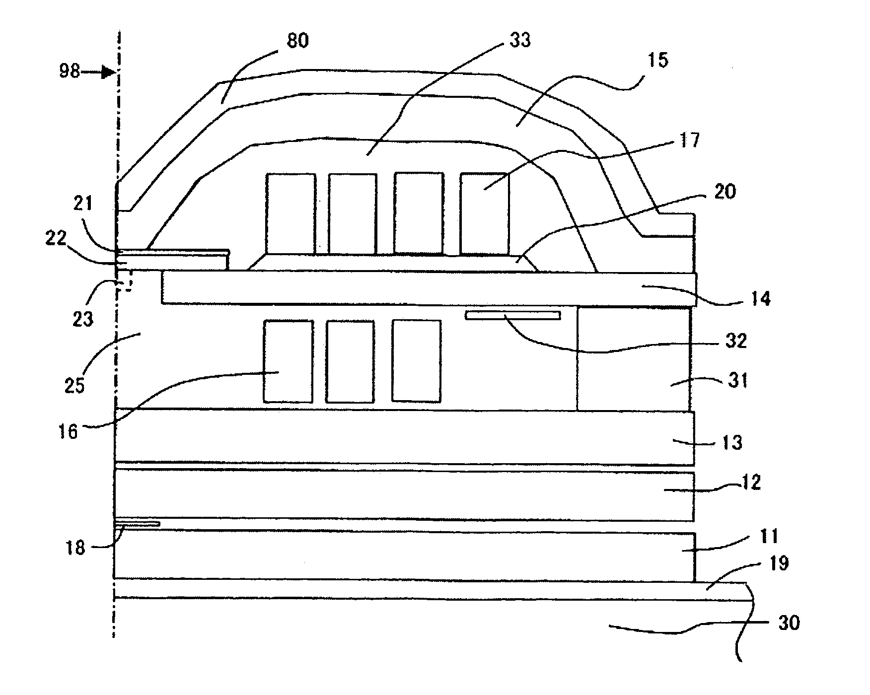
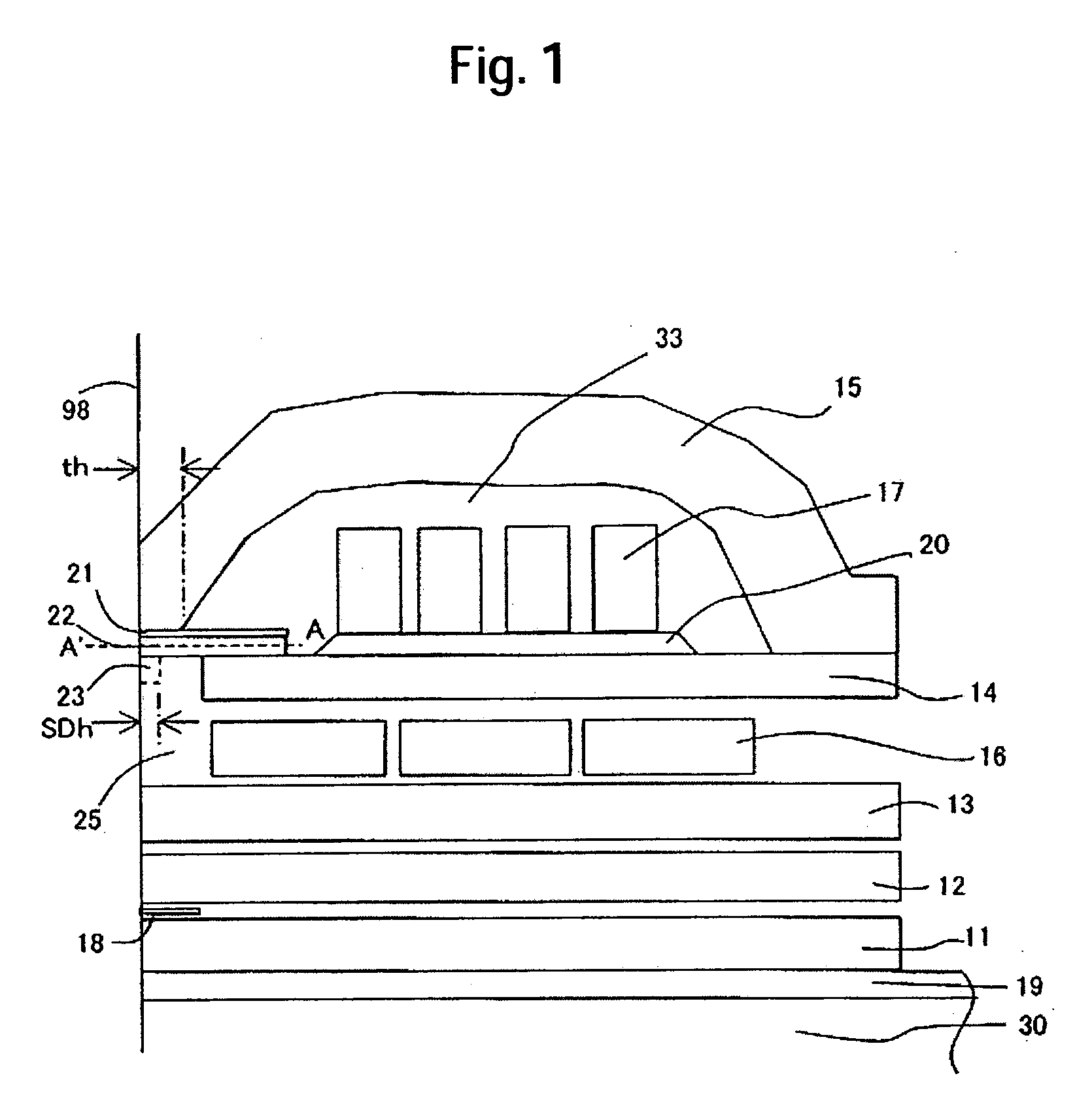
[0070] Embodiment 2 of this invention is a modification of Embodiment. In the same manner as in FIG. 3(a), the flair is formed on the main magnetic pole 22, and the second non-magnetic film 24 contacts the flair. The second non-magnetic film 24 contacts also the first soft magnetic film 23. The first soft magnetic film 23 is enclosed by the second non-magnetic film 24 from at least two directions, and the length in the depth direction of the first soft magnetic film is decided by the second non-magnetic film 24.

[0071]FIG. 4 is diagram showing the structure as viewed from the air bearing surface. A characteristic point is that the non-magnetic film 26 exists between the first soft magnetic film 23 and the second soft magnetic film 15. The second soft magnetic film 15 is magnetically coupled to the soft magnetic film pattern 14 at its rear end as shown in FIG. 1, but the first soft magnetic film 23 and the second soft magnetic film 15 are connected to each other via a magnetic resista...


PUM

PropertyMeasurementUnit
sizesaaaaaaaaaa
sizesaaaaaaaaaa
lengthaaaaaaaaaa

Abstract

Embodiments in accordance with the present invention provide a magnetic head having a narrow track width and excellent in productivity for the purpose of realizing a disk storage unit having a large capacity. In a magnetic head having a plurality of flairs on a main magnetic pole, a side shield is formed via a non-magnetic film on both sides of the flair disposed close to an air bearing surface in such a fashion as to be aligned with the flair.

Description

CROSS-REFERENCES TO RELATED APPLICATIONS [0001] The instant nonprovisional patent application claims priority to Japanese Patent Application No.: 2005-318943, filed Nov. 2, 2005 and incorporated by reference herein for all purposes. BACKGROUND OF THE INVENTION [0002] Embodiments in accordance with the present invention relate to a magnetic head for a disk storage unit using a perpendicular magnetic recording method, particularly, to a write magnetic head structure suitable for recording high density magnetic information on a medium surface and a production method thereof. [0003] A semiconductor memory and a magnetic memory are mainly used for a storage (recording) device of an information appliance. The semiconductor memory is used for an internal storage from the standpoint of access time, and the disk storage unit is used for an external storage from the standpoint of large capacity and nonvolatile properties. A storage capacity is an important index for indicating performance of ...

Claims


Application Information

Patent Timeline
Patent Type & Authority Applications(United States)
IPC IPC(8): G11B5/127
CPCG11B5/11G11B5/1278G11B5/3116G11B5/3146G11B5/3123G11B5/3163
Inventor MARUYAMA, YOJIIWAKURA, TAKAYUKIOHDAKE, ICHIROMOCHIZUKU, MASAFUMI
Owner WESTERN DIGITAL TECH INC
Why Eureka
Try Eureka