Eureka AIR delivers breakthrough ideas for toughest innovation challenges, trusted by R&D personnel around the world.

Methods and apparatus for a redundant board assembly

a technology of redundant boards and assembly methods, applied in the direction of supporting structure mounting, electrical apparatus casings/cabinets/drawers, instruments, etc., can solve the problems of significant cost, board developed according to a later standard cannot be backward compatible with prior cabinets and systems, and cannot be used in applications conforming to subsequent standards. , to achieve the effect of increasing availability and mtbf, the same dimensions and functionality level

Inactive Publication Date: 2007-06-28
THE BOEING CO
View PDF9 Cites 7 Cited by
  • Summary
  • Abstract
  • Description
  • Claims
  • Application Information

AI Technical Summary

Benefits of technology

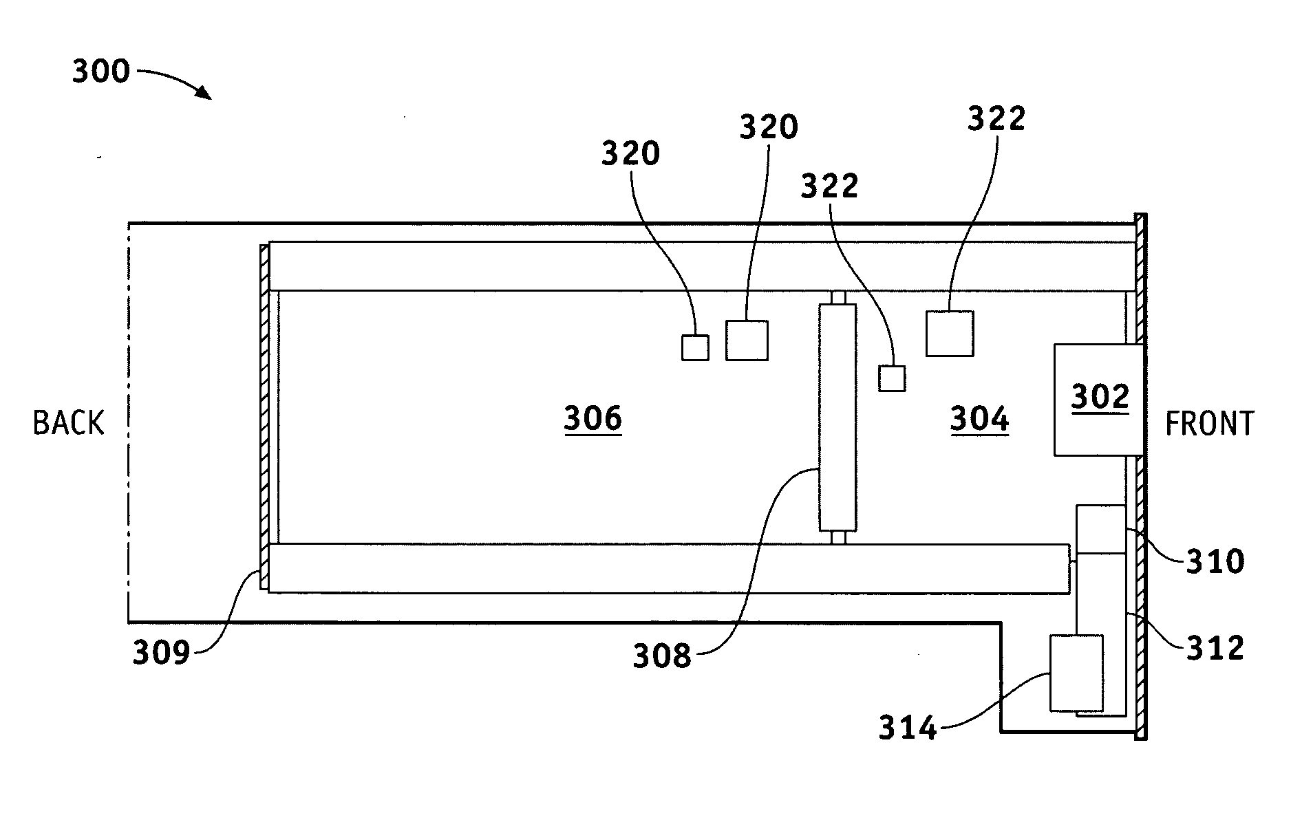
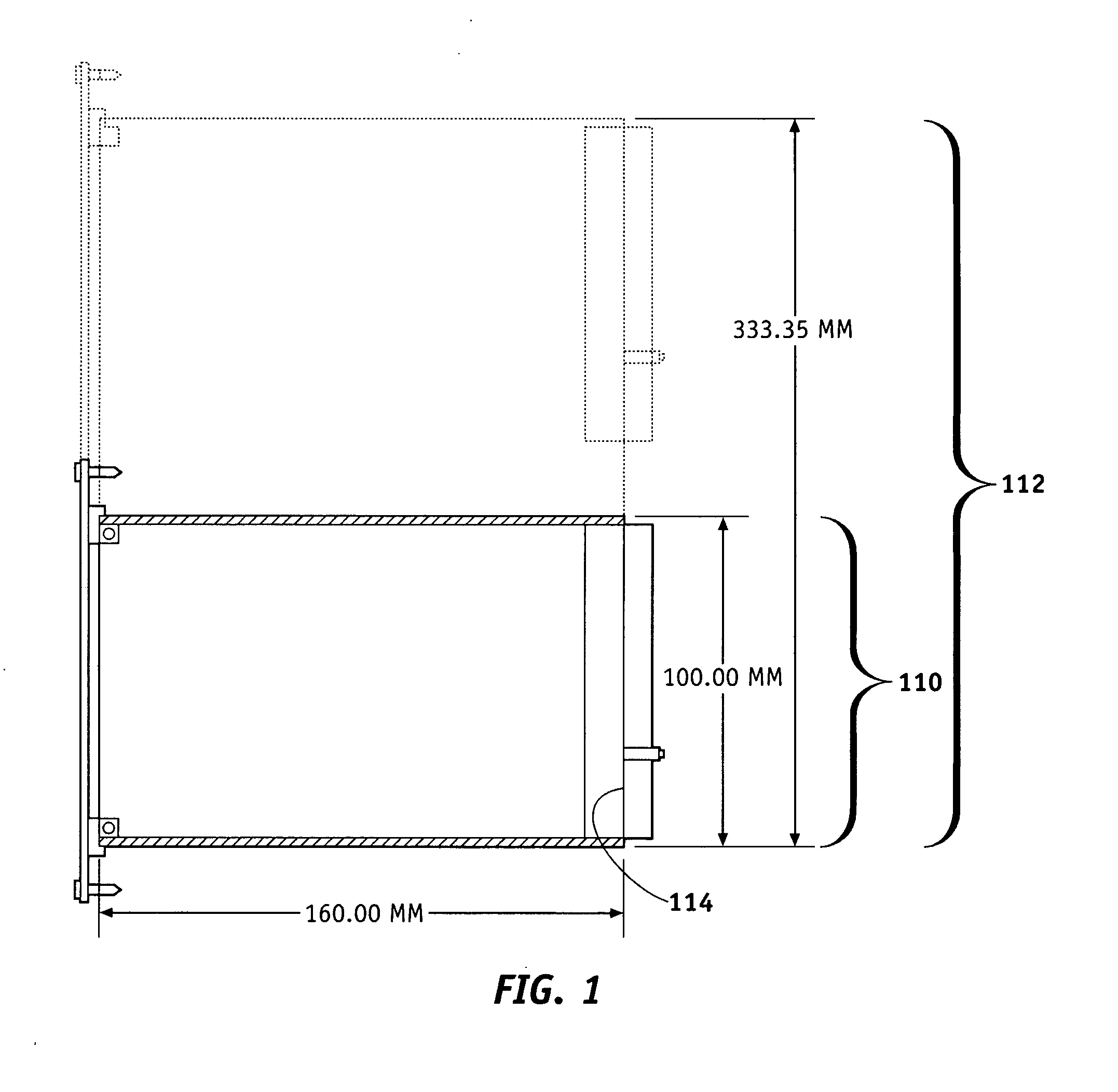
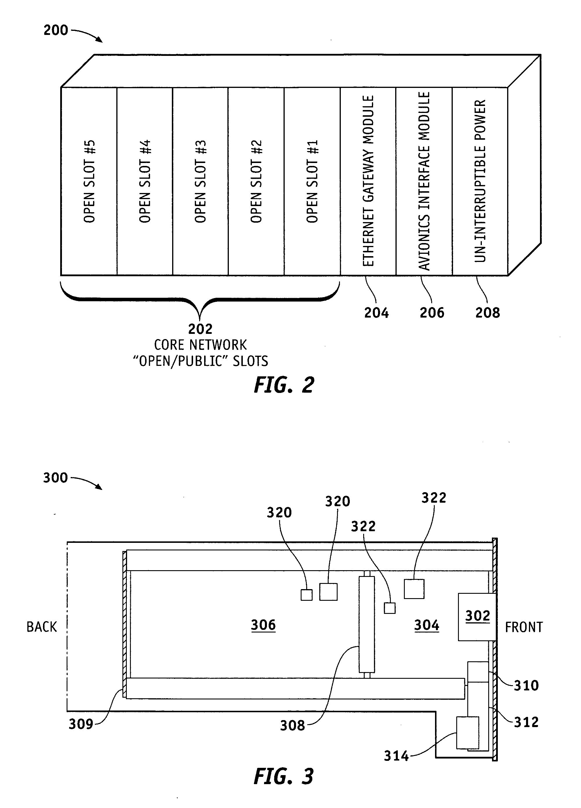
[0006] The invention may be embodied in one form by a redundant pair of interconnected board sub-assemblies that have substantially the same dimensions and level of functionality. A module interconnect card is configured to mechanically and electronically connect to the first and second board sub-assemblies. Each sub-assembly is configured (e.g., via a properly configured microcontroller) to compensate for a loss of functionality in the other sub-assembly. For example, in one embodiment of the present invention, two 3U boards are interconnected for use in a 6U-sized cabinet, thereby increasing the availability and MTBF of the complete assembly.

Problems solved by technology

In this regard, it is often the case that boards developed in accordance with one standard cannot later be used in applications conforming to subsequent standards.
Conversely, a board developed according to a later standard may not be backward-compatible with prior cabinets and systems.
The need to constantly update boards in order to adhere to changing standards gives rise to significant costs.

Method used


Image

  • Methods and apparatus for a redundant board assembly
  • Methods and apparatus for a redundant board assembly
  • Methods and apparatus for a redundant board assembly

Examples


Embodiment Construction

[0014] The following detailed description is merely exemplary in nature and is not intended to limit the invention or the application and uses of the invention. Furthermore, there is no intention to be bound by any expressed or implied theory presented in the preceding technical field, background, brief summary or the following detailed description.

[0015] The invention may be described herein in terms of functional and / or logical block components and various processing steps. It should be appreciated that such block components may be realized by any number of hardware, software, and / or firmware components configured to perform the specified functions. For example, an embodiment of the invention may employ various integrated circuit components, e.g., memory elements, digital signal processing elements, logic elements, look-up tables, or the like, which may carry out a variety of functions under the control of one or more microprocessors or other control devices. In addition, those s...


PUM


Abstract

A redundant pair of interconnected board sub-assemblies have substantially the same dimensions and level of functionality. A module interconnect card is configured to mechanically and electronically connect to the first and second board sub-assemblies. Each sub-assembly is configured (e.g., via a properly configured microcontroller) to compensate for a loss of functionality in the other sub-assembly. Each subassembly preferably includes a re-usable adapter card that interfaces with a first card such that components requiring a lower certification level—e.g., commercial off-the-shelf (COTS) components or the like—may be isolated on the first card, wherein the adapter card includes high certification-level parts and communicates with the first card. The two cards are electronically and mechanically coupled to form the finished board assembly. The interface card may be re-used in a variety of current or future cabinet specifications, including, for example, cabinets manufactured in accordance with the Compact PCI (cPCI) 3U and 6U specifications.

Description

TECHNICAL FIELD [0001] The present invention generally relates to peripheral interface boards and, more particularly, to the use of redundancy in connection with re-usable adapter cards and assemblies. BACKGROUND [0002] In government and commercial systems, it is desirable for interface boards and other such components to be reliable and exhibit a high Mean Time Between Failure (MTBF). Stated another way, it is desirable for interface boards to have a “high availability”—i.e., to be functional and operable within their intended applications. [0003] Furthermore, interface boards must typically conform to one or more standards and / or specifications. These guidelines not only specify the size and shape (i.e., “form factor”) of the board for a particular cabinet or other enclosure, but also set forth power requirements, communication protocols, safety standards, and the like. In this regard, it is often the case that boards developed in accordance with one standard cannot later be used ...

Claims


Application Information

Patent Timeline
IPC IPC(8): H05K5/00
CPCH05K7/1484
Inventor SHEFFIELD, GREGORY L.
Owner THE BOEING CO
Why Eureka
Eureka Blog
Learn More