

Non-magnetic toner, two-component developer, and image forming apparatus
- Summary
- Abstract
- Description
- Claims
- Application Information
AI Technical Summary
Benefits of technology
Problems solved by technology
Method used
Image

Examples
examples
[0107] The invention is described more concretely with reference to the following Examples and Comparative Examples.
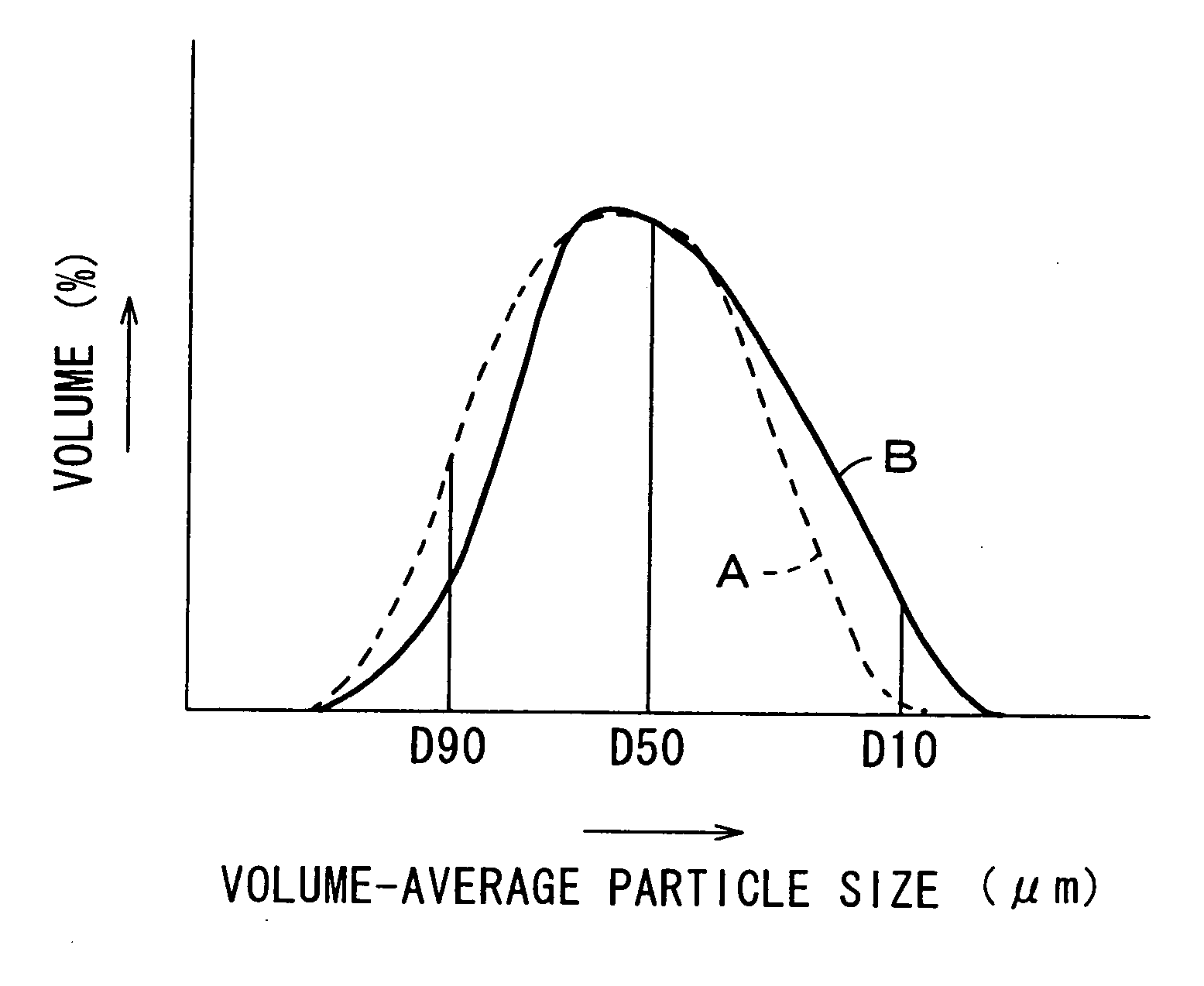
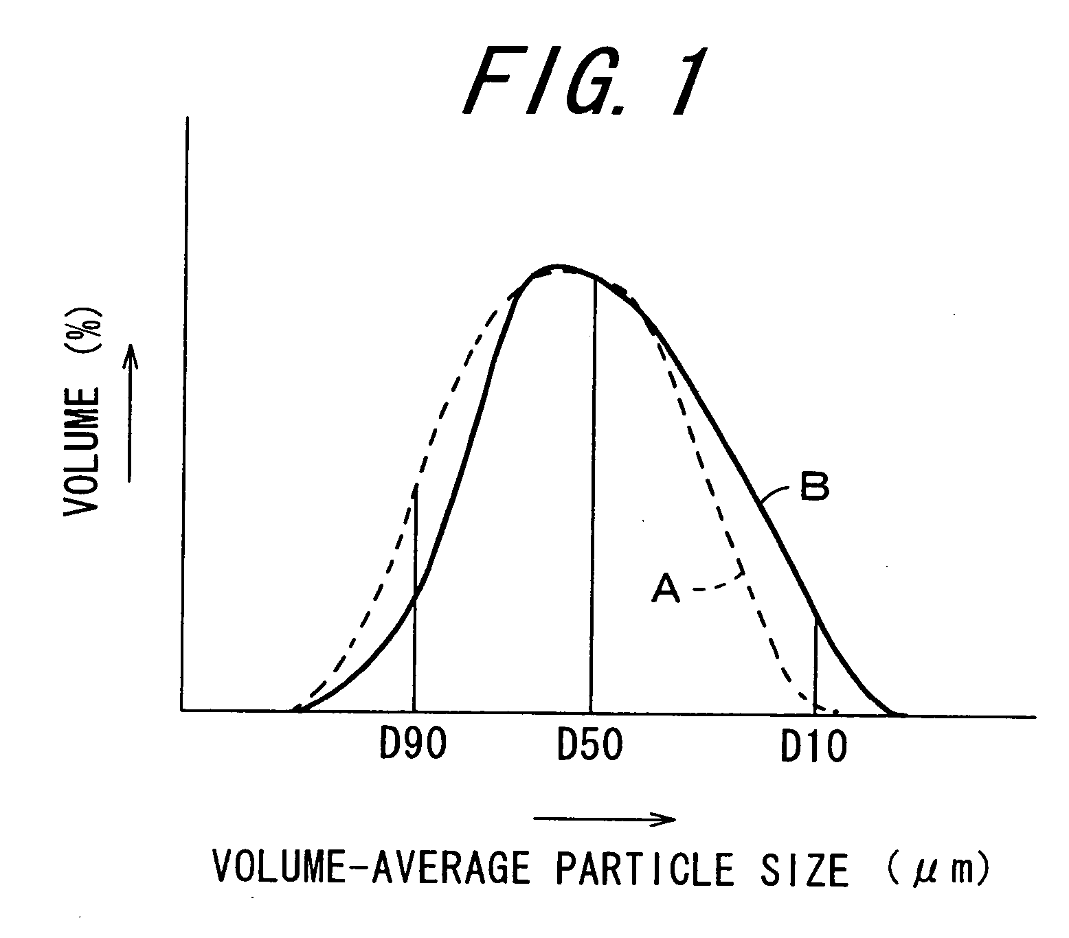
[0108] The particle size and the circularity of the toner particles obtained were determined as follows:
[Method of Particle Size Measurement]
[0109] First prepared is a sample for measurement. 20 ml of an aqueous 1 wt. % solution of sodium chloride (first class grade chemical) (electrolytic solution) is put into a 100-ml beaker. 0.5 ml of alkylbenzenesulfonic acid salt (dispersant) and 3 mg of a toner sample are added thereto in that order and ultrasonically dispersed for 5 minutes. An aqueous 1 wt. % solution of sodium chloride (first class grade chemical) is added thereto to make the overall volume 100 ml, and again ultrasonically dispersed for 5 minutes to prepare a sample for measurement. Using Coulter Counter TA-III (trade name by Coulter), the sample is analyzed under the following condition: the aperture diameter is 100 μm, and the size of the particles to be ...
examples 1 to 20
, and Comparative Examples 1 to 36
[0112]
TABLE 1ColorantType of TonerTypeBlend RatioMagentaC.I. Pigment Red 1224.5 parts by weightCyanC.I. Pigment Blue 15:36.0 parts by weightYellowC.I. Pigment Yellow 175.0 parts by weightBlackCarbon Black5.0 parts by weight
[0113] The blend ratio of the colorant is in terms of the pigment alone. In fact, however, herein used was a master batch containing polyester and one pigment and having a particle size of from 2 to 3 mm, in which the pigment content is 40% by weight of the total amount of the polyester and the pigment.
[0114] 45 kg of a toner material containing 100 parts by weight of a polyester (binder resin, Hymer, trade name by Sanyo Chemical), the predetermined amount of the colorant as in Table 1 and 2.0 parts by weight of zinc salicylate (TN-105, trade name by Hodogaya Chemical Industry) in that blend ratio (by weight) was mixed in a Henschel mixer (FM Mixer, trade name by Mitsui Mining) for 10 minutes. The material mixture was kneaded in ...
examples 21 to 25
, and Comparative Examples 37 to 45
[0119] 100 parts by weight of the magenta toner obtained in Examples 1 to 5 and Comparative Examples 1 to 9, and 1.0 part by weight of negatively-charged hydrophobic silica (volume-average particle size, 10 nm) were mixed in a Henschel mixer for 5 minutes to prepare an external non-magnetic toner. Next, 5 parts by weight of the external non-magnetic toner and 95 parts of a ferrite carrier (volume-average particle size, 45 μm) were mixed in a V-type mixer (V-5, trade name by Tokuju Kosakusho) for 20 minutes to prepare two-component developers of Examples 21 to 25 and Comparative Examples 37 to 45.
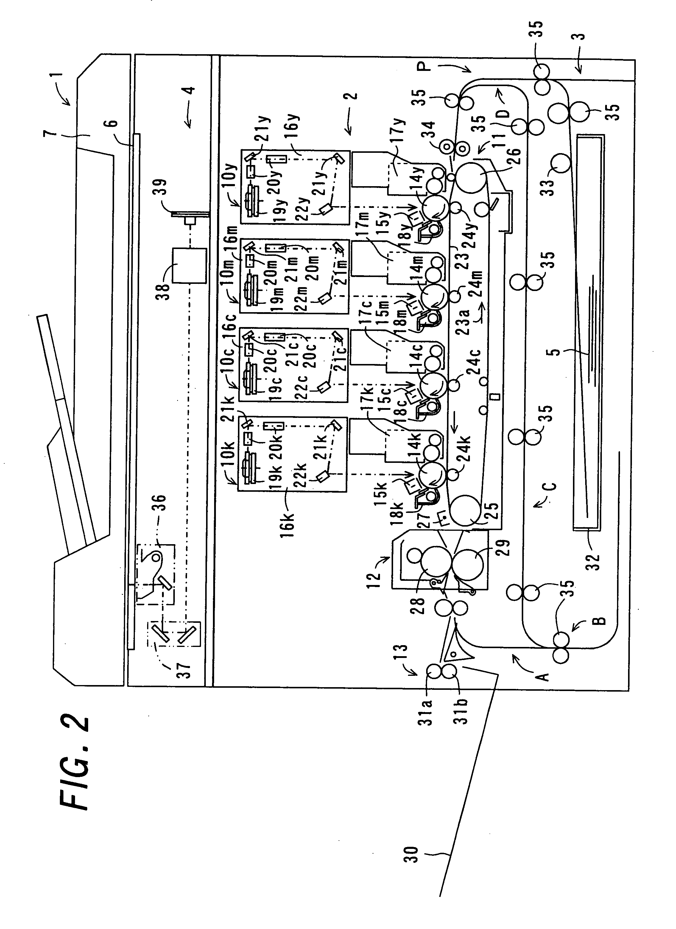
[0120] The two-component developers of Examples 21 to 25 and Comparative Examples 37 to 45 were evaluated for their flowability according to the method mentioned below. In addition, the two-component developer of Examples 21 to 25 and Comparative Examples 37 to 45 was charged in a commercially-available copier (AR-C280, trade name by Sharp—this is an image...
PUM
 Abstract
Description
Claims
Application Information