Method and apparatus for automated grid formation in multi-cell system dynamics models

a multi-cell system and dynamic system technology, applied in the field of computer modeling dynamic systems, can solve the problems of most user-intensive, inaccurate representation of original geometry, and types of problematic cells

Active Publication Date: 2007-06-28
CATERPILLAR INC +1
View PDF15 Cites 24 Cited by
  • Summary
  • Abstract
  • Description
  • Claims
  • Application Information

AI Technical Summary

Benefits of technology

[0009] In one aspect, as embodied and broadly described herein, the method for forming a fixed geometric grid for a fluid dynamics system multi-cell computer model, where the system has one or more surfaces, includes representing the system surfaces by an array of contiguous polygons. The method also includes creating a single model cell that encompasses the entire system and assigning all the surface polygons to the single model cell. The system further includes subdividing at least the portion of the single model cell encompassed by the surface polygon array, including all intersected assigned polygons, using one or more subdividing planes. The method still further includes reassigning all the surface polygons to respective subdivided cells resulting from the subdividing step, identifying those subdivided cells having two or more surface polygons from a common system surface, and calculating effective common boundary areas and normal vectors for the common surface polygons in the identified cells.
[0010] In another aspect, as embodied and broadly described herein, an apparatus for automatically forming a fixed geometric grid for a fluid dynamics system multi-cell computer model, where the system has one or more surfaces, includes a digital computer and a computational fluid dynamics program stored in the computer. The CFD program includes software for receiving a data set representing the system surfaces by an array of contiguous polygons, for creating a single model cell that encompasses the entire system, and for assigning all the surface polygons to the single model cell. The program also includes software for subdividing at least the portion of the single model cell encompassed by the surface polygon array, including subdividing all intersected assigned polygons, using one or more subdividing planes. The program further includes software for reassigning all the surface polygons to respective subdivided cells resulting from the subdividing step, identifying those subdivided cells having two or more surface polygons from a common system surface, and calculating effective boundary areas and normal vectors for those identified cells.

Problems solved by technology

For these CFD programs, the grid or “mesh” generation is the most user-intensive portion of the modeling process, especially for complex geometries with moving boundaries, where the grid may have to be reformed after each transient time step.
In this approach, the original geometry is not accurately represented because information has been lost in the surface approximation.
Cut-cell Cartesian methods can result in two types of problematic cells: “sliver” cells and “split” cells.
Cells with small volumes can require unreasonably small time steps or an unreasonable number of iterations, and therefore more computation, to keep the solution stable.
Split cells also are a problem for logical block structured grids, of which Cartesian is a type.
If a surface of the fluid system to be modeled cuts a Cartesian cell into two or more parts, this presents a problem in conventional CFD codes because there will be two separated cells at the same location.
These two separate cell parts have the same logical coordinates, thus making it impossible for their respective neighbors to locate the appropriate cell part by looking at the logical coordinates alone.
It should be noted that, in some cases, even with user intervention it is not possible to overcome these problems with the more traditional cut-cell approaches.

Method used


Image

  • Method and apparatus for automated grid formation in multi-cell system dynamics models
  • Method and apparatus for automated grid formation in multi-cell system dynamics models
  • Method and apparatus for automated grid formation in multi-cell system dynamics models

Examples


Embodiment Construction

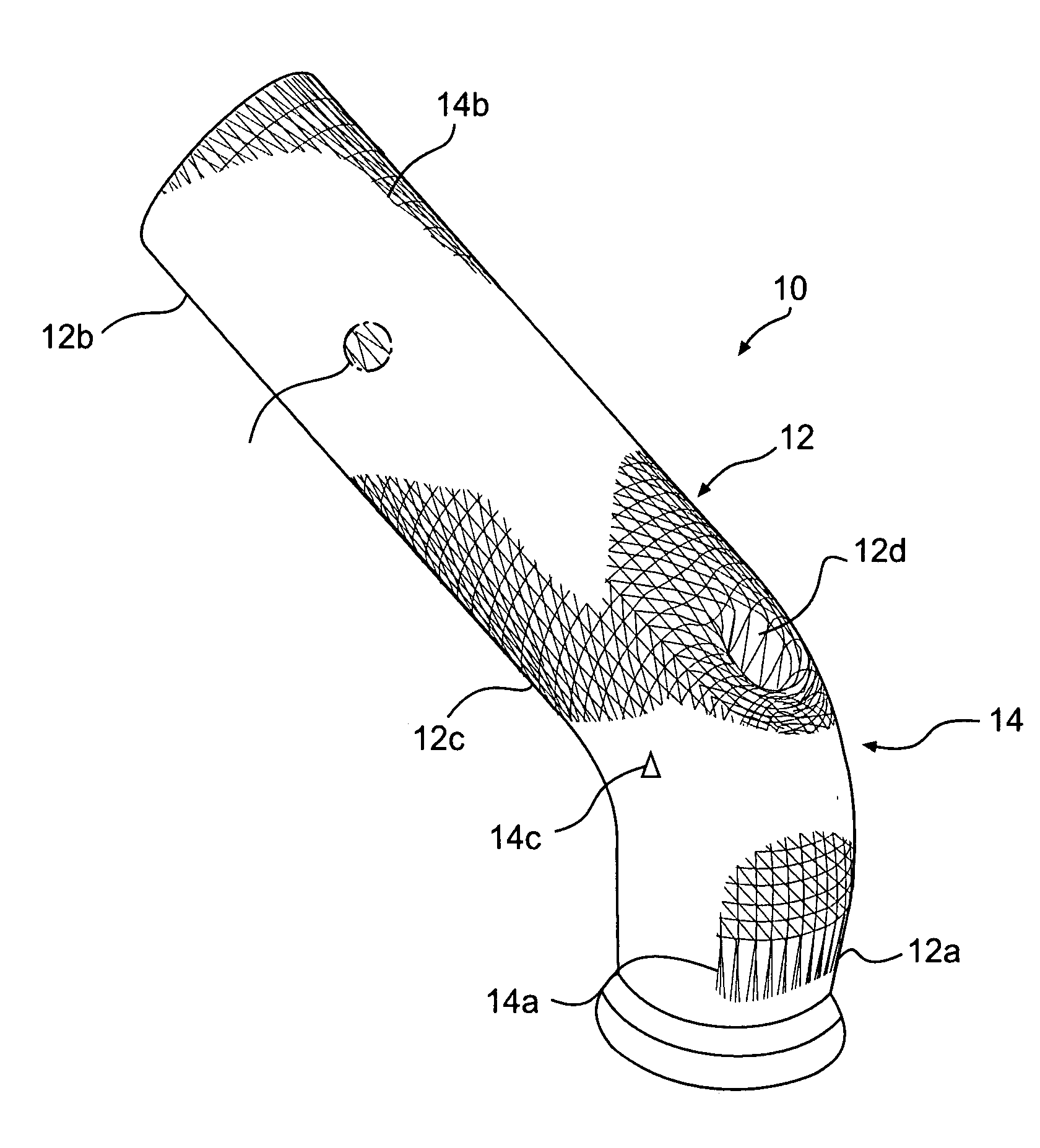
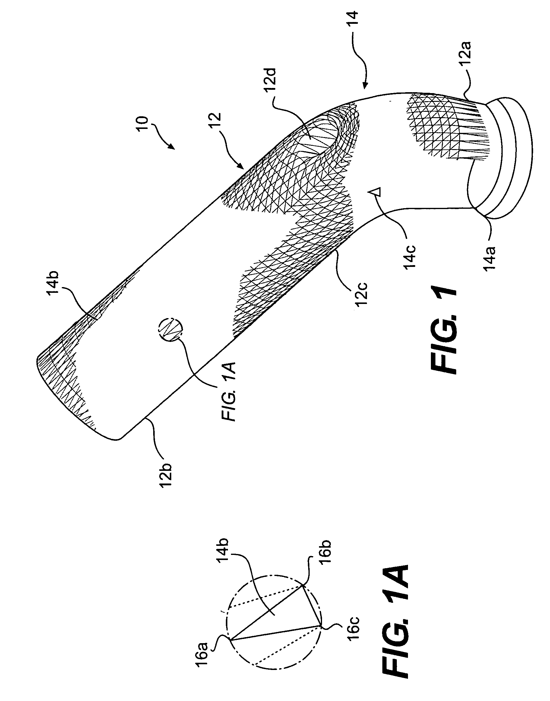
[0021] In one aspect, a method for forming a fixed geometric grid for a fluid dynamic system multi-cell computer model, where the system has one or more surfaces, includes representing the system surfaces by an array of contiguous polygons. As embodied herein, FIG. 1 depicts a header pipe 10 for an internal combustion engine (not shown), where the surface 12 of pipe 10 is “triangulated” for use in forming a model of pipe 10. That is, each part of surface 12 that serves as a boundary for the fluids (gases, liquids, etc.) is covered by an array of individual triangles 14. However, the present method is not limited to the use of triangle-type polygons to represent the system surface.

[0022] The individual triangles of array 14 can be of different sizes, such as triangles 14a and 14b, which are elongated in the relatively straight cylindrical surface sections 12a and 12b of pipe 10, and triangles that are more compact, such as triangles 14c in the curved surface portion 12c of pipe 10. ...


PUM


Abstract

Method for forming a fixed geometric grid for a fluid dynamics system multi-cell computer model, the system having one or more surfaces, includes representing the system surfaces by an array of contiguous polygons. The method also includes creating a single model cell that encompasses the entire system and assigning all the surface polygons to the single model cell. The method further includes subdividing at least the portion of the single model cell encompassed by the surface polygon array, including subdividing all intersected assigned polygons, using one or more subdividing planes. The method still further includes reassigning the surface polygons to respective subdivided cells resulting from the subdividing step, identifying those subdivided cells having two or more surface polygons from a common system surface, and calculating effective common boundary areas and normal vectors for those cells. The method also includes treating “split” cells and “sliver” cells. Apparatus for automatically forming a fixed geometric grid includes a digital computer programmed with a CFD program having software to implement the disclosed method.

Description

TECHNICAL FIELD [0001] The present disclosure relates generally to a method and apparatus for computer modeling dynamic systems such as fluid dynamic systems. More particularly, the present disclosure relates to a method for automated grid formation in multi-cell system dynamics models, and apparatus for performing the method. BACKGROUND [0002] Modeling dynamic systems, including fluid dynamic systems, using computers, particularly high-speed digital computers, is a well known and cost efficient way of predicting system performance for both steady thermophysical and transient conditions without having to physically construct and test an actual system. A benefit to computer modeling is that the effect on performance of changes in system structure and composition can be easily assessed, thereby leading to optimization of the system design prior to construction of a commercial prototype. [0003] Known modeling programs generally use a “multi-cell” approach, where the structure to be mod...

Claims


Application Information

Patent Timeline
Patent Type & Authority Applications(United States)
IPC IPC(8): G06G7/48
CPCG06T17/20G06F30/23
Inventor SENECAL, PETER KELLYPOMRANING, ERIC DOUGLASRICHARDS, KEITH JAREDYANG, TIANLIANG
Owner CATERPILLAR INC
Why Eureka
Try Eureka