Sprayed insulation application system having variably locatable components

a technology of spraying insulation and application system, which is applied in the directions of transportation and packaging, transportation items, loading/unloading vehicle arrangment, etc., can solve the problems of added construction costs, safety hazards, and safety hazards for construction workers

Active Publication Date: 2007-07-05
JOHNS MANVILLE CORP
View PDF4 Cites 13 Cited by
  • Summary
  • Abstract
  • Description
  • Claims
  • Application Information

AI Technical Summary

Benefits of technology

[0013] This invention relates generally to sprayed insulation application systems, and more particularly to systems that utilize a sole power source to directly or indirectly drive the system's multiple components independent of the location of a power-take-off. In one embodiment of the invention, the sprayed insulation application system utilizing a sole power source comprises at least one power-take-off operably associated with the power source. An insulation blower and a hydraulic drive are operably associated with the at least one power-take-off. An electrical generator and a vacuum fan are operably associated with the hydraulic drive, with at least one control regulating the operable association of the generator and the vacuum fan with the hydraulic drive. A liquid pump is optionally operably associated with the hydraulic drive and regulated by the at least one control.

Problems solved by technology

Several disadvantages, however, are associated with the use of use of gasoline engines to power the various components of a sprayed insulation application system.
Because many of the components of such systems are portable to facilitate moving the equipment between insulation application job sites, gasoline must either be provided at a given job site or hauled to and from the job site to fuel the engines, resulting in added construction costs.
Also, because each gasoline engine produces exhaust fumes, the location of a given engine-powered component at a job site may create a safety hazard if the component is located in an enclosed work space where ventilation is limited.
For example, because the application of a sprayed insulation system typically occurs within an enclosed building, the location of a gasoline engine-powered component (i.e. an electrical generator) within the building may create a safety hazard for construction workers located therein due to the accumulation of exhaust fumes.
Furthermore, because the multiple components of a given sprayed insulation application system are often located within the interior of a panel truck box or within the interior of a trailer to facilitate the system's portability, the use of gasoline engines within the confined space of the box or trailer is undesirable as well due to the accumulation of the resultant exhaust fumes.
Several disadvantages, however, are associated with using a truck's PTO to power the various components of a sprayed insulation application system.
To allow the output shaft of the PTO to drive the various components of a sprayed insulation application system, their location must be proximal to that of the output shaft, thus limiting the variability of the location of each component.
However, the central location of one or more components (i.e. the electrical generator, liquid pump and / or vacuum fan) about the main drive shaft of a truck may not be desirable where such components are preferably located remotely of the box of the truck during the insulation application process (i.e. within the building enclosure receiving the insulation), or where their central location within a truck's box is either impractical or inconvenient.

Method used


Image

  • Sprayed insulation application system having variably locatable components
  • Sprayed insulation application system having variably locatable components
  • Sprayed insulation application system having variably locatable components

Examples


Embodiment Construction

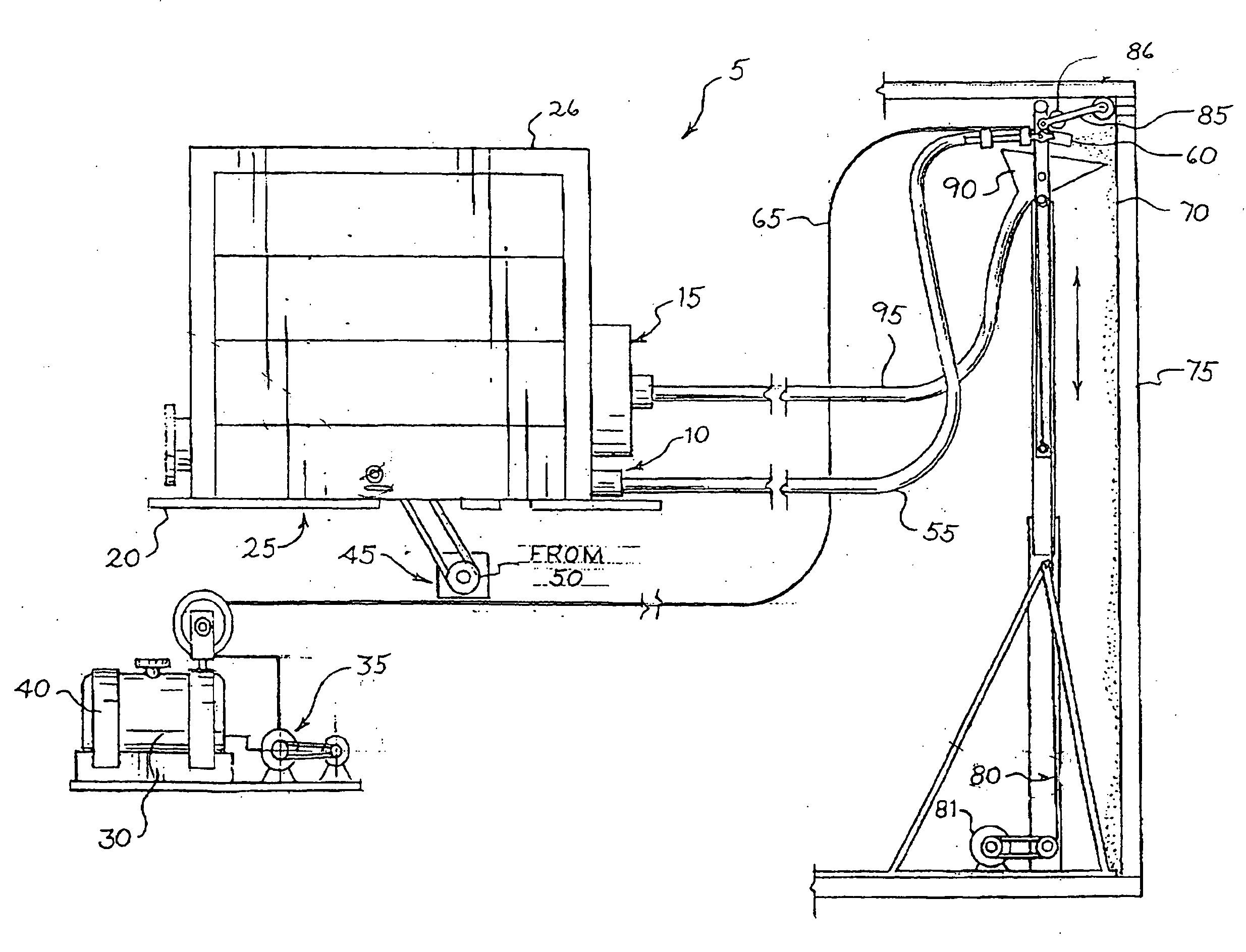
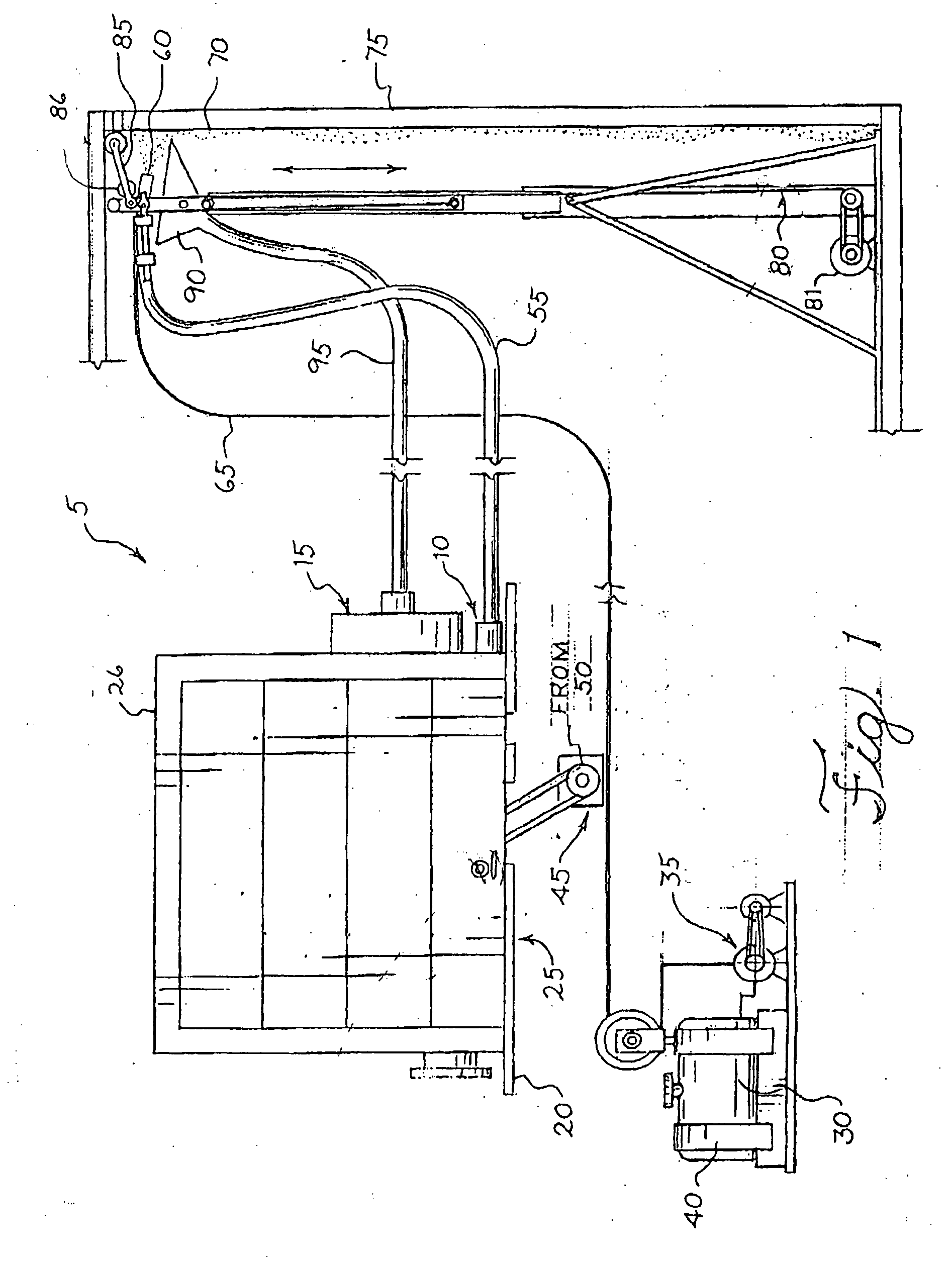
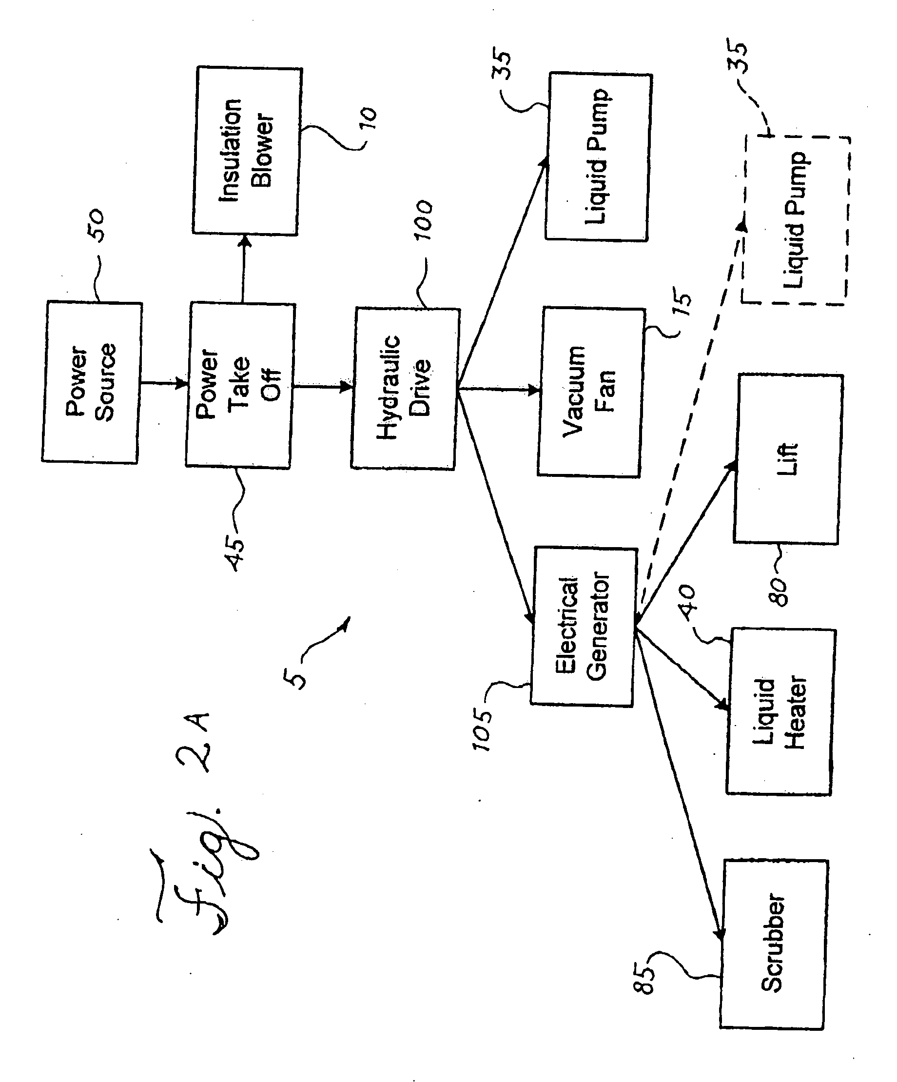
[0033] This invention relates generally to sprayed insulation application systems, and more particularly to systems that utilize a sole power source to directly or indirectly drive the system's multiple components independent of the location of a power-take-off. Prior to discussing how the sprayed insulation application system is powered in accordance with the present invention, a discussion of the system's powered components is in order. FIG. 1 thus illustrates the basic components of a preferred embodiment of a sprayed insulation application system 5 that is powered in accordance with the present invention.

[0034] As illustrated therein, an insulation blower 10 and a vacuum fan 15 are preferably located on the bed 20 of a truck 25 (truck viewed from the rear with the wheels and axle omitted for clarity), preferably within the truck's box 26, while a liquid reservoir 30 and pump 35, for storing and conveying water or a liquid adhesive utilized by the system, are preferably located ...


PUM


Abstract

This invention relates generally to sprayed insulation application systems, and more particularly to systems that utilizes a sole power source to directly or indirectly drive the system's multiple components independent of the location of a power-take-off. In one embodiment of the invention, the system utilizing a sole power source comprises at least one power-take-off operably associated with the power source. An insulation blower and a hydraulic drive are operably associated with the at least one power-take-off. An electrical generator and a vacuum fan are operably associated with the hydraulic drive, with at least one control regulating the operable association of the generator and the vacuum fan with the hydraulic drive. In another embodiment of the invention, the hydraulic drive is operably associated with the power-take-off, with the generator, vacuum fan and insulation blower operably associated with the hydraulic drive. The electrical generator, driven by the generator hydraulic motor in fluid communication with the hydraulic drive, preferably provides electrical energy to the scrubber, and to the at least one liquid heater and/or the electrically powered lift, if utilized within the system, via electrical conduits. A pump may be optionally driven by the hydraulic drive or energized by the generator.

Description

TECHNICAL FIELD OF THE INVENTION [0001] This invention relates generally to sprayed insulation application systems, and more particularly to systems that utilize a sole power source to directly or indirectly drive the system's multiple components independent of the location of a power-take-off. BACKGROUND OF THE INVENTION [0002] Sprayed insulation is commonly used in the construction industry for insulating the open cavities of building walls, floors, ceilings, attics and other areas. Insulation materials, such as loose fiberglass, rock wool, mineral wool, fibrous plastic, cellulose, ceramic fiber, etc. that is combined with an adhesive or water, are sprayed into such open cavities to reduce the rate of heat loss or gain there-though. The adhesive properties of the insulation mixture, comprising the insulation combined with adhesive or water, allow it to adhere to vertical or overhanging surfaces, thus allowing for an application of insulation prior to the installation of wallboard ...

Claims


Application Information

Patent Timeline
Patent Type & Authority Applications(United States)
IPC IPC(8): E04F21/00
CPCE04F21/085Y10T74/20024Y10T74/2003
Inventor FELLINGER, THOMAS J.
Owner JOHNS MANVILLE CORP
Why Eureka
Try Eureka