Device for rapidly chilling articles in a refrigerator

a technology for refrigerators and articles, applied in domestic refrigerators, domestic cooling appliances, lighting and heating appliances, etc., can solve the problems of bursting of containers, reducing the temperature of soda cans to an acceptable level, and consuming a lot of time. , to achieve the effect of lowering the temperature of containers

Active Publication Date: 2007-07-05
MAYTAG
View PDF29 Cites 78 Cited by
  • Summary
  • Abstract
  • Description
  • Claims
  • Application Information

AI Technical Summary

Benefits of technology

[0010] In further accordance with the invention, the carriage includes a cylindrical support wall that defines an article receptacle. The support wall is provided with a plurality of openings that allow cooling air to flow from the air channel into the article receptacle. A fan is provided that draws in cooling air from the refrigerator that is then directed through the air channel into the carriage. In addition to the fan, the beverage chiller includes a motor operatively connected to the carriage. The motor is selectively activated to rotate the carriage in the central cavity. A plurality of rollers, at least one of which is driven by the motor, support and drive the carriage about a substantially horizontal axis. With this arrangement, a beverage container placed within the carriage is rotated, while the cooling airflow is directed over the container. The combined rotation and airflow impingement rapidly lowers a temperature of the container.

Problems solved by technology

Waiting for a container that is simply placed into a refrigerator to chill is quite often too time consuming.
For example, lowering the temperature of a can of soda to an acceptable level can take many hours.
Placing the can in a freezer to speed the process can lead to bursting of the container.
That is, if left unchecked, the contents can freeze and expand, resulting in bursting of the can.
While effective to a degree, guiding air currents over the surface of a container in this manner does not result in the most efficient transfer of energy.

Method used


Image

  • Device for rapidly chilling articles in a refrigerator
  • Device for rapidly chilling articles in a refrigerator
  • Device for rapidly chilling articles in a refrigerator

Examples


Embodiment Construction

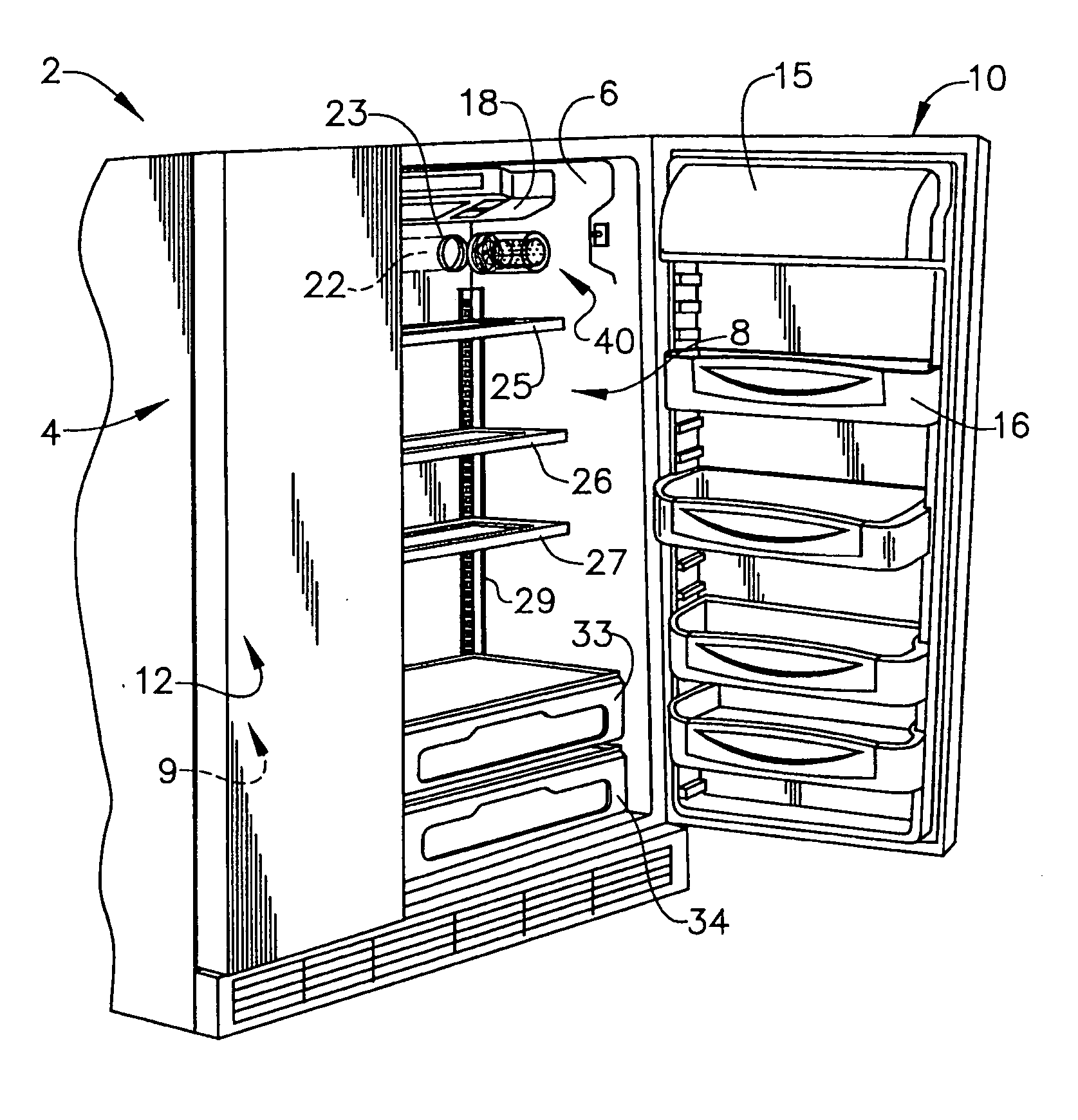
[0017] With initial reference to FIG. 1, a refrigerator 2 includes an outer shell or cabinet 4 within which is positioned a liner 6 defining a fresh food compartment 8. A corresponding liner (not shown) defines a freezer compartment 9. In a manner known in the art, fresh food compartment 8 can be accessed by the selective opening of a fresh food door 10. In a similar manner, a freezer door 12 can be opened to access freezer compartment 9. For the sake of completeness, fresh food door 10 of refrigerator 2 is shown to include a dairy compartment 15 and various vertically adjustable shelving units, one of which is indicated at 16.

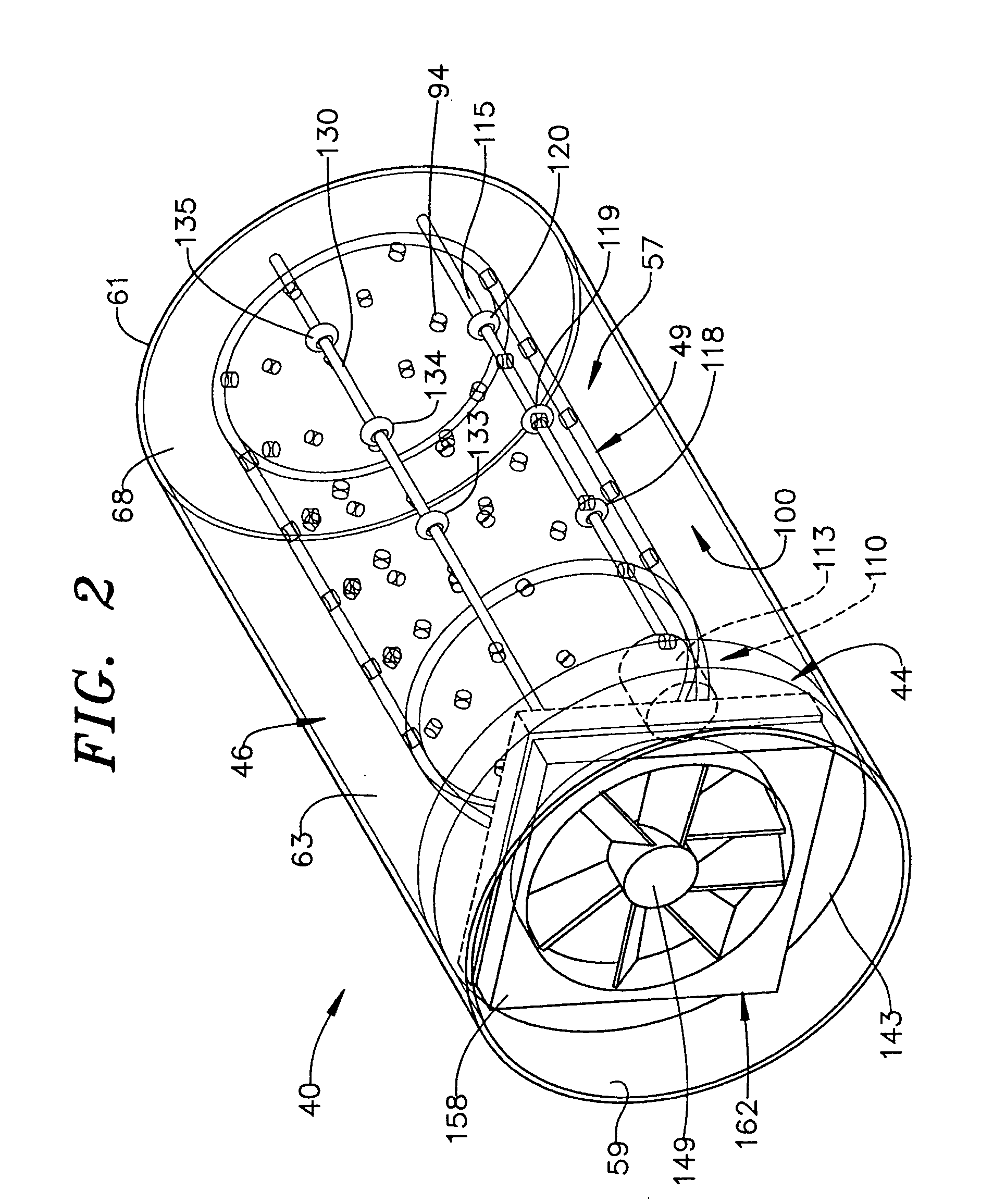
[0018] Mounted in an upper region of fresh food compartment 8 is a temperature control housing 18. Extending laterally across fresh food compartment 8, below temperature control housing 18, is a duct 22 having an outlet 23 that is in fluid communication with freezer compartment 9 of refrigerator 2. Also shown below temperature control housing 18 are a plurali...


PUM


Abstract

A device for rapidly chilling containers in a refrigerator includes a base portion, an outer body portion and a carriage. The outer body portion includes an outer shell defining a central cavity. The carriage is rotatably supported in the central cavity and spaced from the outer shell so as to define an air channel. The carriage includes a support wall that defines an article receptacle. The support wall includes a plurality of openings that open to the air channel. A fan is provided to establish a cooling airflow that is directed through the air channel into the carriage. A motor is employed to selectively rotate the carriage. A plurality of rollers, at least one of which is driven by the motor, support and drive the carriage to rotate through the cooling airflow to rapidly lower the container temperature.

Description

BACKGROUND OF THE INVENTION [0001] 1. Field of the Invention [0002] The present invention pertains to the art of refrigerators and, more particularly, to a device provided in a compartment of a refrigerator for rapidly lowering a temperature of an article placed therein. [0003] 2. Discussion of the Prior Art [0004] There has long been a demand for rapidly cooling beverage containers and the like. Whether the need is for quickly cooling a can or bottle of soda, chilling a bottle of wine or the like, consumers have a need for a device that will quickly chill a warm beverage. Waiting for a container that is simply placed into a refrigerator to chill is quite often too time consuming. For example, lowering the temperature of a can of soda to an acceptable level can take many hours. Placing the can in a freezer to speed the process can lead to bursting of the container. That is, if left unchecked, the contents can freeze and expand, resulting in bursting of the can. Towards that end, man...

Claims


Application Information

Patent Timeline
Patent Type & Authority Applications(United States)
IPC IPC(8): F25D17/04F25D17/06F25D11/02
CPCF25D2400/28F25D2400/30F25D2700/06F25D2331/805F25D31/007F25D2317/061F25D2331/803F25D17/065
Inventor FREESMEIER, JONFU, XIAOYONG
Owner MAYTAG
Why Eureka
Try Eureka