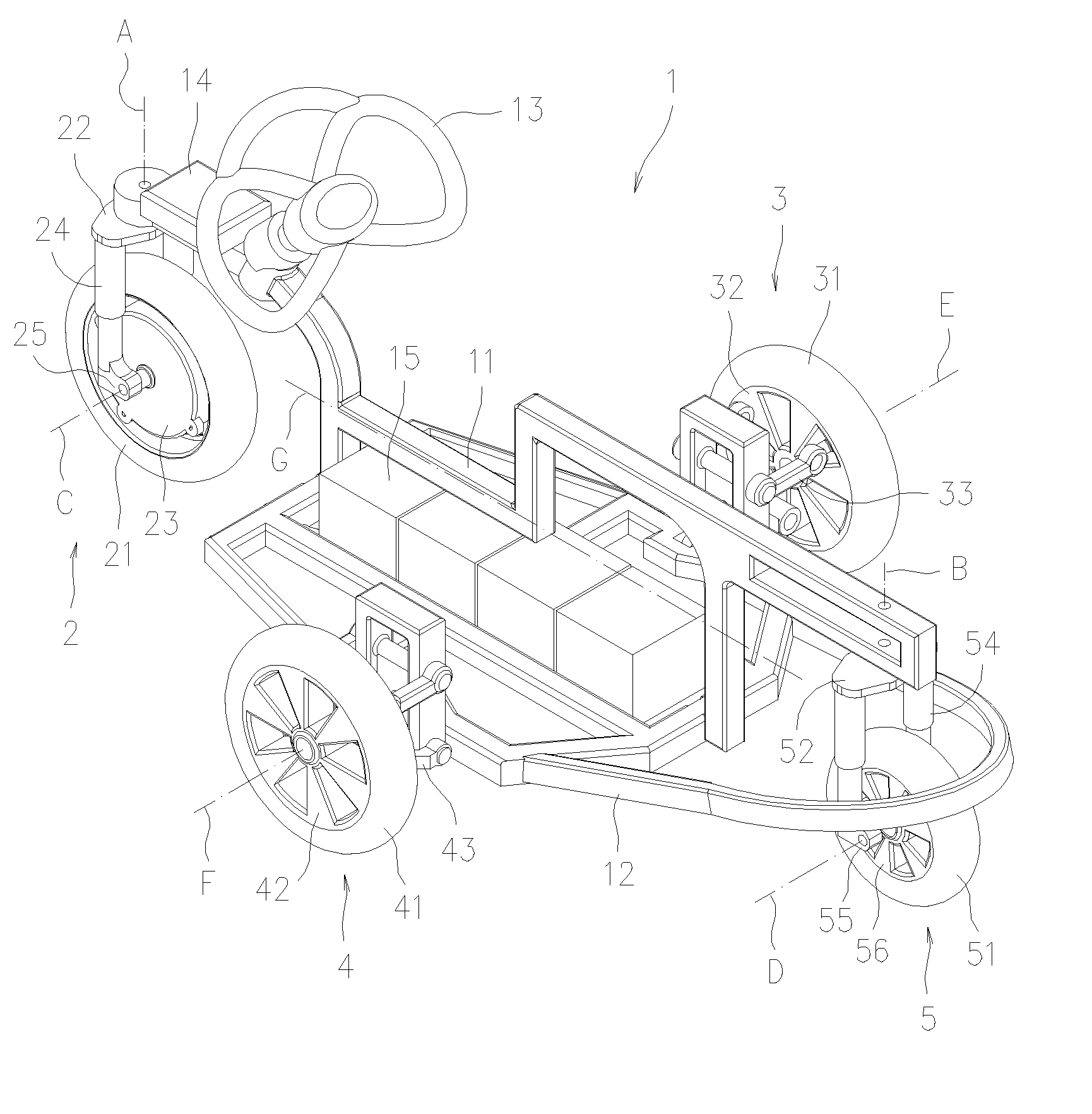
[0029]Referring to FIGS. 5-7, which are respectively a perspective view, a top plan view and a side elevation view of a wheel arrangement for a four-wheeled vehicle in accordance with a preferred embodiment of the present invention. The four-wheeled vehicle 1 includes a vehicle frame 11 and a chassis 12. Wherein, the front wheel unit 2, having a front wheel 21 and a pivoting axis A, is disposed at the front of the vehicle frame 11 by connecting the same to the front segment of the vehicle frame 11 using a supporting base 22. In addition, the vehicle frame 11 further comprises a steering device 13 (illustrated as a shape of a steering wheel, shown in FIG. 1), which is connected to the front wheel unit 2 through a switching mechanism 14. It is noted that the switching mechanism 14 can be a mechanical structure or an electronic or electrical system. A driver can control the steering device 13 to drive the front wheel unit 2 to steer around the pivoting axis A through the switching mechanism 14. The maximum steering angle of the front wheel unit 2 is no more than 90 degrees to the right or 90 degrees to the left. The front wheel unit 2 further includes a shock absorber 24 having a resilient member and a damper (not shown). The shock absorber 24 is disposed between the supporting base 22 and a shaft supporting portion 25 connecting the axis C of the front wheel 21. The point of the pivoting axis A of the front wheel unit 2 projected on the ground is biased from the point of the axis C of the front wheel 21 projected on the ground by a distance C′ (as shown in FIG. 7). Therefore, the reacting force at the ground-touching point of the front wheel 21 and the moment caused by the biased distance C′ enable the front wheel unit to keep progressing straightly. A hub motor 23 is disposed at the front wheel 21, which is powered by a battery pack 15 disposed on the vehicle frame 11. The driver can control the hub motor 23 to drive the four-wheeled vehicle 1 to move, which is prior art and so is not described herein. It is noted that the front wheel 21 can be driven by a motor-in-wheel instead of the hub motor 23.
[0030]Furthermore, right and left side wheel units 3, 4 are respectively disposed at opposite sides of a middle segment of the vehicle frame 11. The right side wheel unit 3 includes a right side wheel 31, a hub 32, and a suspension system 33. The right side wheel 31 can roll freely around the axis E thereof. The suspension system 33 is connected with the chassis 12 to enable the right side wheel unit 3 to be an independently suspended and freely rolling wheel unit. Similarly, the left side wheel unit 4 includes a left side wheel 41, a hub 42, and a suspension system 43. The left side wheel 41 can freely roll around the axis F. The suspension system 43 is connected with the chassis 12 to enable the left side wheel unit 4 to be an independently suspended and freely rolling wheel unit. The axis E of the right side wheel unit 3 and the axis F of the left side wheel unit 4 are collinear and are perpendicular to the longitudinal axis G of the vehicle frame 11. The axis E and the axis F are not connected directly.
[0031]Secondly, a rear wheel unit 5 is disposed at the rear of the vehicle frame 11, which includes a rear wheel 51 and a pivoting axis B. The rear wheel unit 5 is connected to the rear segment of the vehicle frame 11 by another supporting base 52. The rear wheel unit 5 may be steered freely within 360 degrees about the axis B. The rear wheel unit 5 further includes a shock absorber 54 having a resilient member and a damper (not shown). The shock absorber 54 is disposed between the supporting base 52 and a shaft supporting portion 55 connecting the axis D of the rear wheel 51. The axis D is biased from the pivoting axis B of the rear wheel unit 5 by a distance D′ (as shown in FIG. 7). The hub 56 can freely steer about the axis D. When the four-wheeled vehicle 1 progresses, the force from the ground-touching point of the rear wheel 51 and the moment caused by the biased distance D′ enables the rear wheel unit 5 to freely rotate about the axis B. Thus, the rear wheel unit 5 can adjust itself to align to the progressing direction of the vehicle 1.
[0032]Referring to FIGS. 6 and 7, it must be illuminated that in accordance with the four-wheeled vehicle formed by the front wheel unit 2, the right side wheel unit 3, the left side wheel unit 4 and the rear wheel unit 5, the pivoting axis A, B of the front and rear wheel units 2, 5 are located on the longitudinal axis G of the vehicle frame 11, and the right and left side wheel units 3, 4 are isometrically disposed at the opposite sides of the longitudinal axis G of the vehicle frame 11. Thus, the distance D1, D2, respectively measured from the front wheel unit 2 to the right side wheel unit 3 and the left side wheel unit 4, are equal. The distance D3, D4, respectively measured from the rear wheel unit 5 to the right and left side wheel units 3, 4, are equal. When the axis E, F locate at the center of the front and rear wheel units 2, 5, the wheelbase a of the front wheel and the wheelbase b of the rear wheel are equal, and the distance D1˜D4 of the wheel units are equal thereby forming a rhombus wheel arrangement. Contrarily, when the front wheelbase a and the rear wheelbase b are not equal, a diamond wheel arrangement is formed (as shown in the dashed of FIG. 6). Furthermore, the front and rear wheelbase a, b are configured equal or unequal in accordance with the requirement of the actual driving performance of the four-wheeled vehicle and the difference of application manner. However, the CG(center of gravity position) H must be configured between the axis C of the front wheel and the axis E, F of the side wheels.
[0033]Compared with the conventional rhombus vehicle (as shown in FIGS. 1-4), since the rear wheel unit 5 of the present invention can freely steer and can forward the CG to the front wheelbase a, the load of the front wheel unit 2 may be configured to be relatively larger, which fits to front wheel drive and so prevents skid of the front wheel drive wheel. Further referring to FIG. 8, when the four-wheeled vehicle of the present invention turns (illustrating status of turning left), the rolling axis C, D, E, F of the four wheels 21, 31, 41, 51 meet at a same turning center I thereby avoiding unstable oversteering caused by interference of side forces of the four wheels 21, 31, 41, 51 during negotiating a turn. Referring to FIG. 9, when the front wheel 21 is perform a near 90 degrees left turn which is perpendicular to the longitudinal axis G of the vehicle frame, the right side wheel 31 is rolling forward and the left side wheel 41 is rolling opposite thereto while the rear wheel 51 is free to be steer following the direction of the turn. Thus, the four-wheeled vehicle 1 can perform a turn-in-spot, i.e. a stationary turn of gyration. When the front wheelbase a is larger than the rear wheelbase b, the turning radius of the stationary turn of gyration of the four-wheeled vehicle 1 is almost equal to the front wheelbase a.
[0034]Referring to FIG. 10A showing a schematic view of a rhombus four-wheeled vehicle of the present invention, and FIG. 10B showing a schematic view of a conventional rectangle four-wheeled vehicle, the front and rear wheelbase L6 and the right and left side tread W6 of the rhombus four-wheeled vehicle 6 are equal to the front and rear wheelbase L7 and the right and left side tread W7 of the rectangle four-wheeled vehicle 7. Regarding to the static safety factor (SSF), higher SSF means stronger anti-rolling and anti-overturn capability. The value of the SSF, in rectangular vehicle, is equal to the ratio of the length W of a perpendicular line from the CG to the connection line of the front and rear wheels to height h of the CG, that is, SSF=W/h. Therefore, when the height of the CG is the same, the longer length W of the perpendicular line from the CG to the connection line of the front and rear wheels means the larger SSF. As shown in FIGS. 10A and 10B, when the height of the CG is the same, the perpendicular line V7 from the CG H7 of the rectangle four-wheeled vehicle to the connection line of the front and rear wheels is longer than the perpendicular line V6 from the CG H6 of the rhombus four-wheeled vehicle to the connection line from the front and side wheels whereby the value of SSF of the rectangle four-wheeled vehicle is larger than that of the rhombus four-wheeled vehicle. As to a small size vehicle with a narrow vehicle frame, that is treads W6, W7 of the right and left side wheels are narrow, the difference of the value of SSF of the rectangle four-wheeled vehicle and the rhombus four-wheeled vehicle is very small. As shown in FIGS. 10A and 10B, while performing a station turn of gyration, the turning radius R6 of the rhombus four-wheeled vehicle is slightly smaller than the turning radius R7 of the rectangle four-wheeled vehicle (the length from the CG to the wheel 71). When the rectangle four-wheeled vehicle 7 needs the four wheels 71˜74 to simultaneously turn, the front wheels 71, 72 must turn to be toe-in, and the rear wheels 73, 74 must turn to be toe-out, which requires extremely complicated mechanism and control and even adversely affects the wheel position. When the rhombus four-wheeled vehicle 6 of the present invention is performing a station turn of gyration, only the steering of the front wheel 61 is under control, the other three wheels 621864 can roll freely, and the rear wheel can self-steer (simultaneously referring to FIG. 9) whereby it does not need an additional mechanism and driving force for controlling. Accordingly, as to the function of station turn of gyration, the rhombus four-wheeled vehicle of the present invention is advantageous.
[0035]Referring to FIG. 11A showing a schematic view of a rhombus four-wheeled vehicle, and FIG. 11B showing a schematic view of a conventional three-wheeled vehicle, the front and rear wheelbase L6 and the right and left side tread W6 of the rhombus four-wheeled vehicle 6 are equal to the front and rear wheelbase L8 and the right and left side tread W8 of the three-wheeled vehicle 8. To consider drivability and prevent from backwards inclining during accelerating, the CG H8 of the three-wheeled vehicle 8 must be moved forwards. Since the rhombus four-wheeled vehicle 6 has the rear wheel 64, the CG H6 of the rhombus four-wheeled vehicle can be configured to extremely close the axis E, F of the two side wheels 62, 63. Thus, when the heights of the CGs are equal, the value of the SSF of the rhombus four-wheeled vehicle 6 is greater than that of the three-wheeled vehicle whereby the rhombus four-wheeled vehicle has more anti-rolling capability.
[0036]Referring to FIGS. 12A and 12B, as shown in FIG. 12A (simultaneously referring to FIG. 9) the front and rear wheelbase L6 and the right and left side tread W6 of the rhombus four-wheeled vehicle 6 are equal to the front and rear wheelbase L8 and the right and left side tread W8 of the three-wheeled vehicle 8. When the front wheel 61 of the rhombus four-wheeled vehicle 6 of the present invention is turned 90 degrees and the rear wheel 64 reversely turns 90 degrees for performing a station turn of gyration, the turning radius R6 of the vehicle 6 is the front wheelbase a. When the three-wheeled vehicle 8 is performing a station turn of gyration as the front wheel turns 90 degrees, the turning radius R8 is the wheelbase L8 of the front and rear wheels as the front wheel 81 is the driving wheel and the rear wheels can freely roll. Comparatively, since the front and rear wheelbase L6 of the rhombus four-wheeled vehicle 6 is equal to the front and rear wheelbase L8 of the three-wheeled vehicle 8, the turning radius R6 of the rhombus four-wheeled vehicle 6 is half of the turning radius R8 of the three-wheeled vehicle 8 thereby greatly reducing space for turning.
[0037]Further referring to FIG. 5, in the preferred embodiment, the front wheel unit 2 has the driving force, and the steering operation device 13 is operated to steer the front wheel unit 2 through the switching mechanism 14. The right and left side wheel units 3, 4 and the rear wheel unit 5 can freely roll. It must be noted that besides the above arrangement, the front wheel unit 2 may be configured to steer only, the right and left wheel units 3, 4 are configured as driving wheels, and the rear wheel unit 5 is configured to steer freely, or the front wheel unit 2, the right and left side wheel units 3, 4 are configured as driving wheels, the front wheel unit 2 is still configured to steer and the rear wheel unit 5 is configured to steer freely, or the front and rear wheel units 2, 5 are configured to steer freely, the right and left side wheel units 3, 4 are configured as driving wheels, but the wheel units 3, 4 can individually control power output, rolling direction and speed. The power transmission, speed and direction of rotation of the foregoing driving wheel can be controlled through a driving control unit or mechanism (not shown, belonging to prior art and so not described herein). When the driver controls steering operation device 13, the driver intent can be transmitted to the control unit through the switching mechanism 14. When the front wheel unit 2 turns approximately 90 degrees, the driving control mechanism of the right and left side wheel units 3, 4 can be actuated to enable one of the right and left side wheel units 3, 4 to forwards roll and the other to rearwards roll whereby the four-wheeled vehicle can fix a position to turn in place. The power and rotation speed of the right and left side wheel units 3, 4 decide the vehicle to straightly progress, steer or performing a stationary turn of gyration. When the front and rear wheel units 2, 5 both can steer freely, the front wheel can naturally turn to the progressing direction during swerving or performing a stationary turn of gyration without additional driving mechanism.
[0038]As described above, the wheel arrangement for a four-wheel vehicle of the present invention has a rhombus or diamond configuration and can have the same radius of turning in place as a rectangle four-wheeled vehicle having switching mechanism for turning in place without additional steering control mechanism when the length of the vehicle frames or the wheelbases of the present invention and the conventional four-wheeled vehicle are equal. Compared with a three-wheeled vehicle, the wheel arrangement for a four-wheel vehicle of the present invention has more advantages. The wheel arrangement for a four-wheel vehicle of the present invention upgrades drivability and motility. The streamline shaped four-wheeled vehicle of the invention has a low wind resistance coefficient which greatly reduces fuel consumption during high speed traveling. The wheel arrangement for a four-wheel vehicle of the present invention is especially fitted to be applied by small size vehicles since the vehicles of such wheel arrangement occupy less road area and thus increase using efficiency of a road while increasing flow of vehicles traveling thereon.
[0039]While the preferred embodiment of the invention has been set forth for the purpose of disclosure, modifications of the disclosed embodiment of the invention as well as other embodiments thereof may occur to those skilled in the art. Accordingly, the appended claims are intended to cover all embodiments which do not depart from the spirit and scope of the invention.