Preservation skid

a technology of skids and skid bodies, applied in the field of skids, can solve the problems of time-consuming operation, high labor intensity, and high cost of preventing corrosion of assets, and achieve the effects of reducing time and personnel, reducing the risk of injury, and ensuring safety

Inactive Publication Date: 2007-07-05
SMITH RUSSELL LOUIS +1
View PDF13 Cites 11 Cited by
  • Summary
  • Abstract
  • Description
  • Claims
  • Application Information

AI Technical Summary

Benefits of technology

[0006] The object of this invention is to provide a skid and cover system that reduces the amount of time and personnel required to pack an asset for export shipment or long-term preservation, and also reduce the risk of injury to installation personnel. To accomplish those goals it was determined that the necessity of installing bolts, over which an asset would be lowered and then fastened to a skid must be eliminated. Installation of a flexible base sheet as an integral part of a skid is the first step towards accomplishing the goals. Hermetic “factory mounting” of an upper tier, to a skid (on top of the base sheet), provides a surface onto which an asset may be bolted without “field-penetrating” the flexible base sheet and without needing to have the bolts protruding from up under the deck. The asset can simply be placed upon the deck of the upper tier, drilling can be done right through the asset's feet and upper deck and then bolts can be installed with a much higher degree of speed and safety (see FIG. 4). Another method of goal attainment is to produce a skid; again with a pre-installed hermetically sealed base sheet, with an additional layer of decking (machine platform) mounted directly on top of the flexible base sheet. In this case, bolt-holes are drilled from the upper-most layer (machine platform) through the deck and out the bottom of the stringers. Carriage bolts are then inserted through all components of the skid; stringers, deck boards, base sheet, resilient gaskets with silastic calk and upper machine platform, such that the bolts protrude up through the top of the skid. Eye nuts are then tightened to the bolts which securely fasten all skid components together. With this system in use an installation crew need not drill any holes nor install any bolts whatsoever. The asset is simply placed upon the upper deck (flanked by the eye nuts) and then heavy duty ratchet straps are utilized to secure the asset to the skid (see FIGS. 7 and 9). In both styles sited above, the flexible base sheet is produced and installed such that its outer edges extend out beyond the outer edges of the skid. This positioning of the base sheet allows for the un-obstructed lowering of a flexible cover, down over the asset for alignment with and heat-sealing to the base sheet. Utilization of this invention has been shown to significantly reduce installation time, reduce installation personnel requirements, and greatly minimizes the risk of crushing, pinching and amputation injuries.

Problems solved by technology

The traditional method(s) of preventing corrosion on assets involves costly labor intensive and sometimes dangerous procedures.
This operation is time consuming, and if the base sheet becomes torn or otherwise damaged it must be replaced with a new one.

Method used


Image

  • Preservation skid
  • Preservation skid
  • Preservation skid

Examples


Embodiment Construction

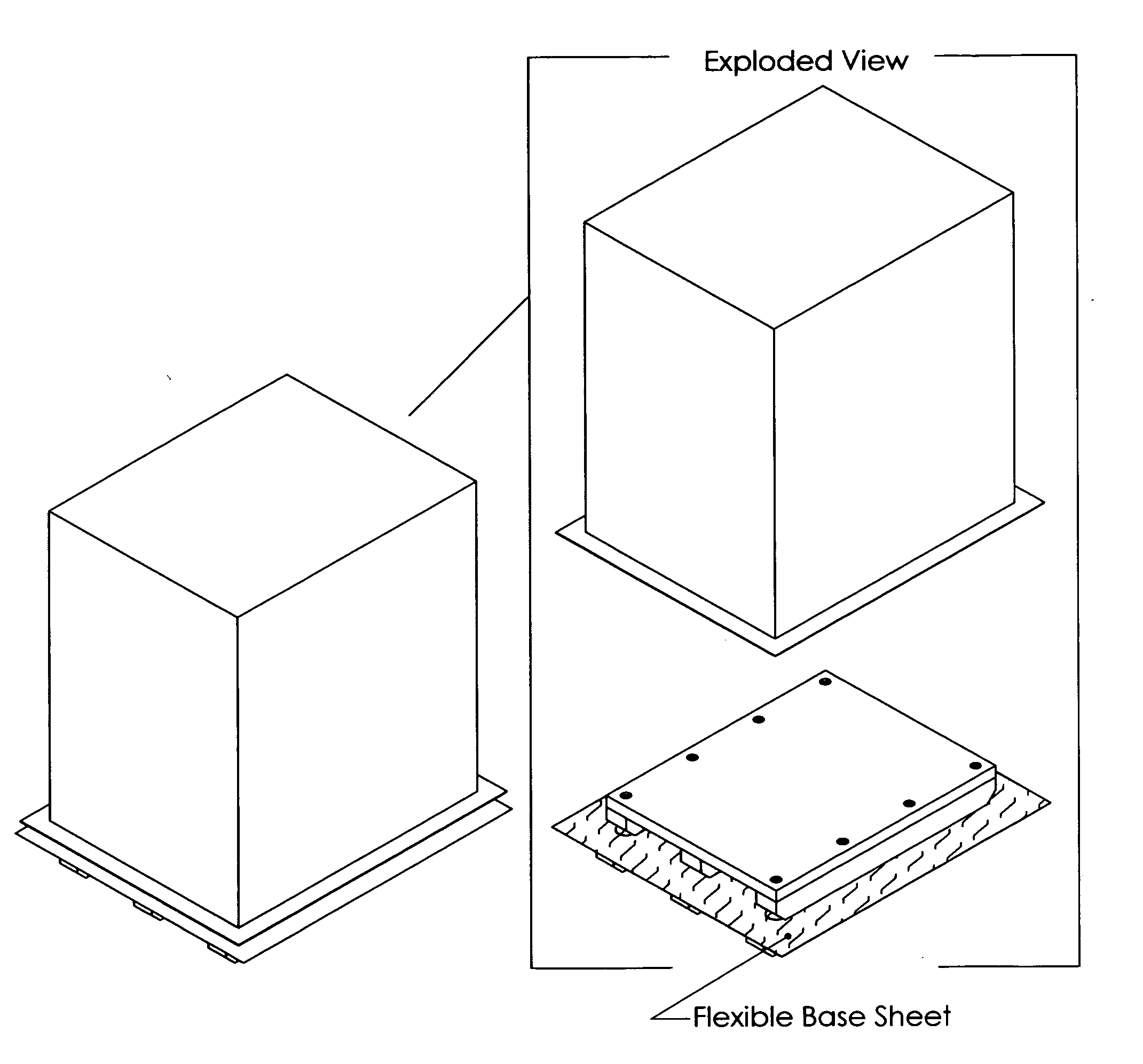
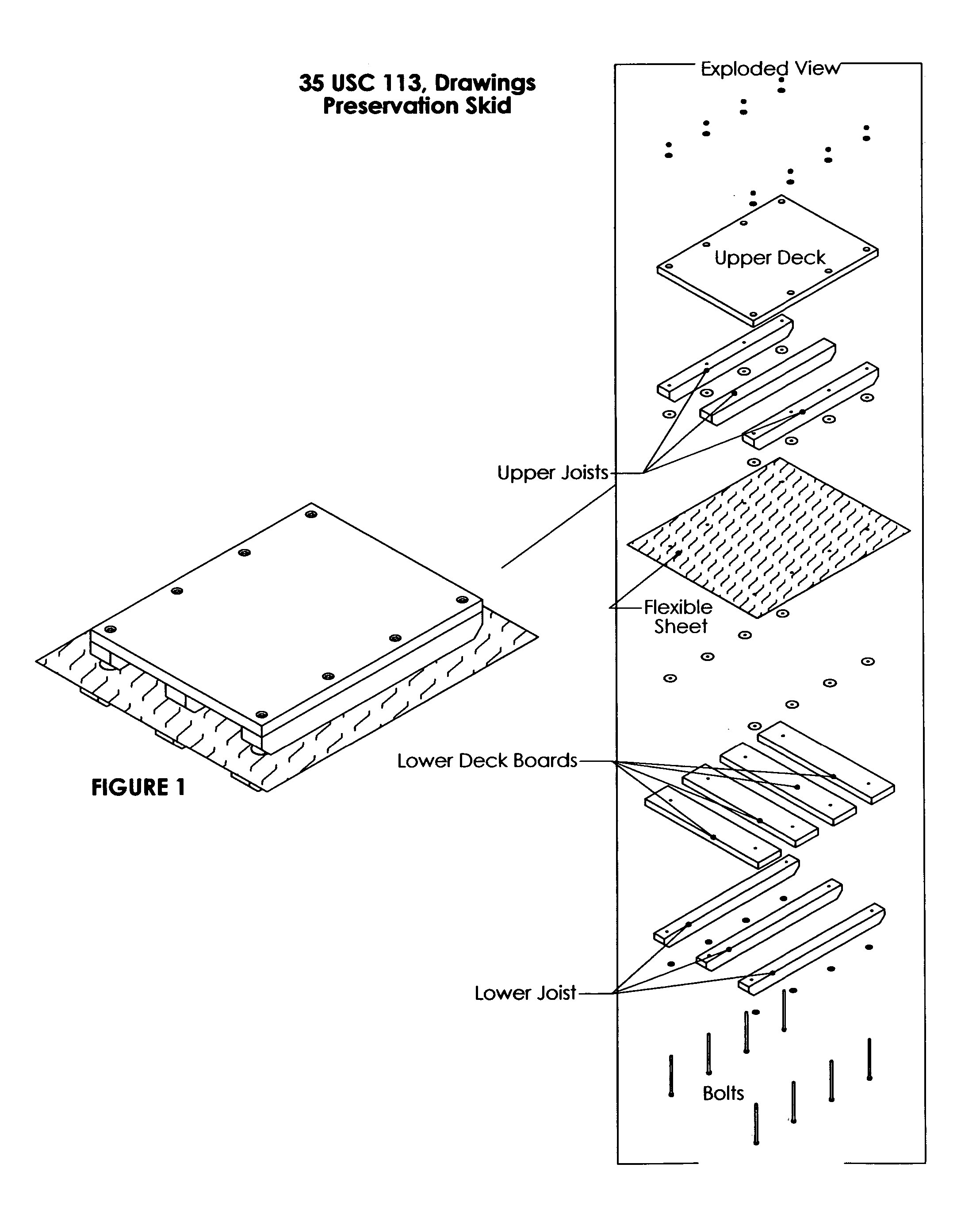
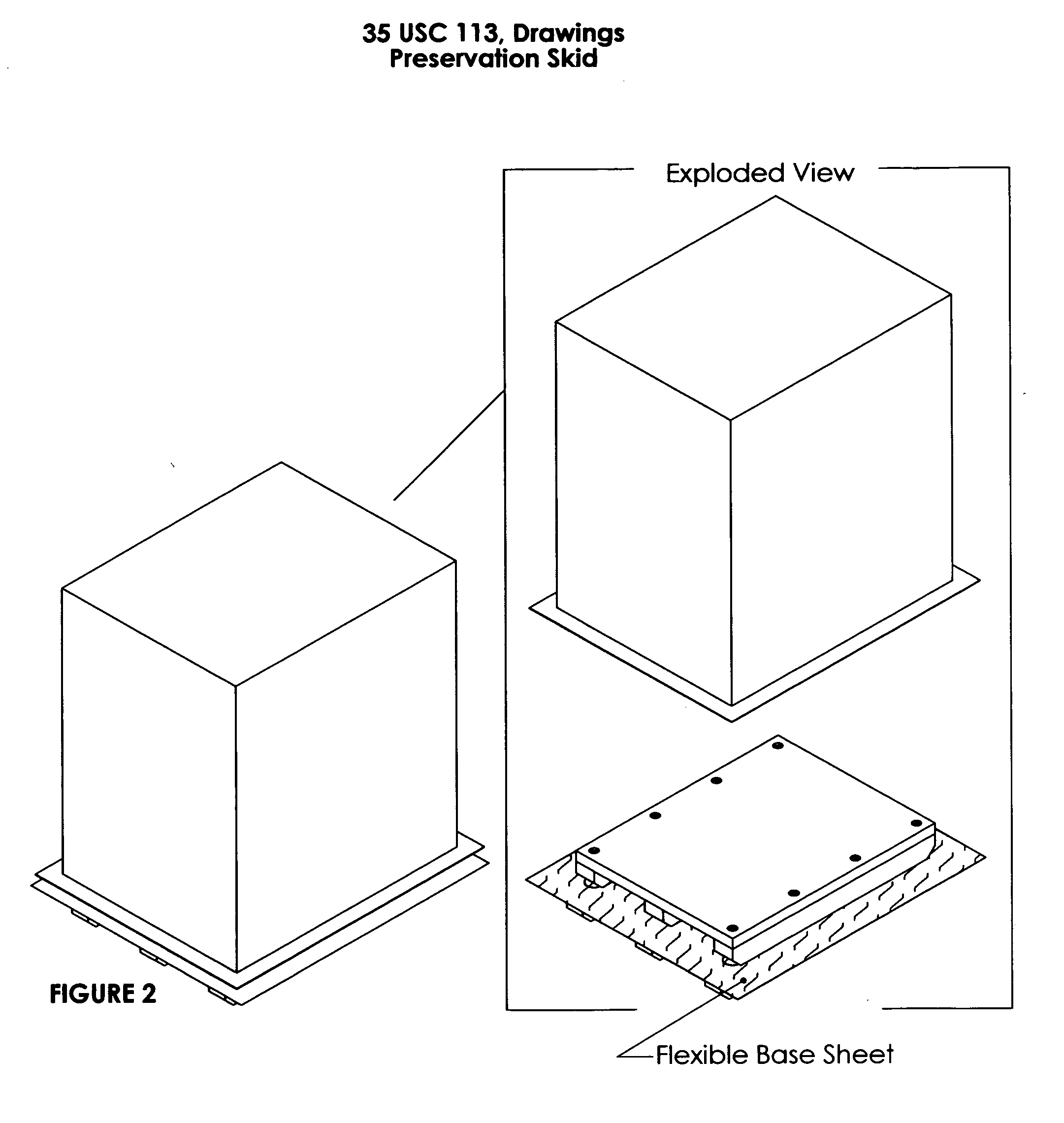
[0017] This invention is comprised of a skid which has a sheet of flexible packaging material “sandwiched” between two layers of rigid material in a hermetic or air-tight fashion, and that extends out beyond the edges of the rigid materials (see FIGS. 1, 5, 7 and 8). For the purpose of this description, a skid shall be defined as an assembly of rigid parts onto which an asset or product may be placed for the purpose of moving the asset or product. The skids construction shall consist of two or more stringers that are placed upon the floor, all in parallel alignment with one another and of sufficient thickness so as to allow a lifting device (such as the forks of a lift truck of pallet jack) to fit between the stringers and beneath deck boards which get fastened to the upper faces of the stringers. The deck boards shall be positioned at 90° to the stringers and all deck boards shall be parallel to one another (see FIG. 3).

[0018] This invention can be configured in numerous ways. One...


PUM


Abstract

This invention is a skid or pallet that arrives at a “using location” with a pre-installed hermetically integrated base sheet, produced from a flexible packaging material. It is built, such that one of several methods of securing any given asset to the skid can be utilized in a fashion that eliminates the possibility of compromising the integrity, or air-tightness, of the base sheet. An asset(s) can be secured to the invention rapidly with minimal labor expenditures without worrying about, precision registration of machine feet with skid bolts or the dangers associated with manual guidance of equipment over protruding bolts. This invention can reduce the amount of time spent in the preparation of an asset for export shipment or placement into long-term storage multi-fold; due to the elimination of measuring, punching, drilling, calking and alignment operations all of which will save money and enhance employee safety protection.

Description

CROSS-REFERENCE TO RELATED APPLICATIONS [0001] This specification is now being filed (during the pending period) of the earlier filed Provisional Application having a filing date of Dec. 30, 2004 and which was assigned Application No. 60 / 640,007 with Confirmation Number 3626 and Filing Receipt #OC000000015019597. It is my intention to take benefit from said earlier filing. STATEMENT REGARDING FEDERALLY SPONSORED RESEARCH OR DEVELOPMENT [0002] Not Applicable REFERENCE TO SEQUENCE LISTING, A TABLE, OR A COMPUTER PROGRAM LISTING COMPACT DISC APPENDIX [0003] Not Applicable BACKGROUND OF THE INVENTION [0004] The field of endeavor to which this invention pertains is the prevention of rust, corrosion or oxidation from occurring on the metal parts of an asset while said asset is in storage or during transport. Manufacturers of assets, that include but are not limited to, industrial machinery, computers and components thereof, aircraft and component parts, commercial equipment etc. etc., go ...

Claims


Application Information

Patent Timeline
Patent Type & Authority Applications(United States)
IPC IPC(8): B65D19/00
CPCB65D19/40B65D19/44B65D2519/00104B65D2519/0086B65D2519/00373B65D2519/00572B65D2519/00711B65D2519/00273
Inventor SMITH, RUSSELL LOUISSMITH, WILLIAM STUART
Owner SMITH RUSSELL LOUIS
Why Eureka
Try Eureka