Three-phase opposite rotating motor and fan

Active Publication Date: 2007-07-05
DELTA ELECTRONICS INC
View PDF20 Cites 34 Cited by
  • Summary
  • Abstract
  • Description
  • Claims
  • Application Information

AI Technical Summary

Benefits of technology

[0008] In order to achieve the above objects, the stator of the invention comprises at least one three-phase coil set having three solenoids. When the motor is turned on, one solenoid of the three-phase coil set of the stator inducts the distribution of the line of magnetic force of the first and second rotors and generates an inversely electronkinetic potential in order to determine the direction of current of another solenoids, i.e., to determine the direction of excitation of the other solenoids. The excited solenoids together with the first and second rotors generate a magnetic effect to rotate the first and second rotors. In particular, the ratio of the number of solenoids of the three-phase coil set to that of the first poles of the first rotor is 3:4, and the ratio of the number of solenoids of the three-phase coil set to that of the second poles of the second rotor is 3:2, ensuring the motor works normally in an opposite rotating operation. Based on the ratio of the number of the first poles of

Problems solved by technology

However, these fans occupy a larger space and require a lengthy installation process, and the auxiliary fan increases the manufacturing cost.
Further, it is possible that the resistance between the primary and auxiliary fans may be increased, so that the airflow cannot be efficiently raised because they are independent from each other.
The electrodes and the

Method used


Image

  • Three-phase opposite rotating motor and fan
  • Three-phase opposite rotating motor and fan
  • Three-phase opposite rotating motor and fan

Examples


Embodiment Construction

[0021] The following description is of the best-contemplated mode of carrying out the invention. This description is made for the purpose of illustrating the general principles of the invention and should not be taken in a limiting sense. The scope of the invention is best determined by reference to the appended claims.

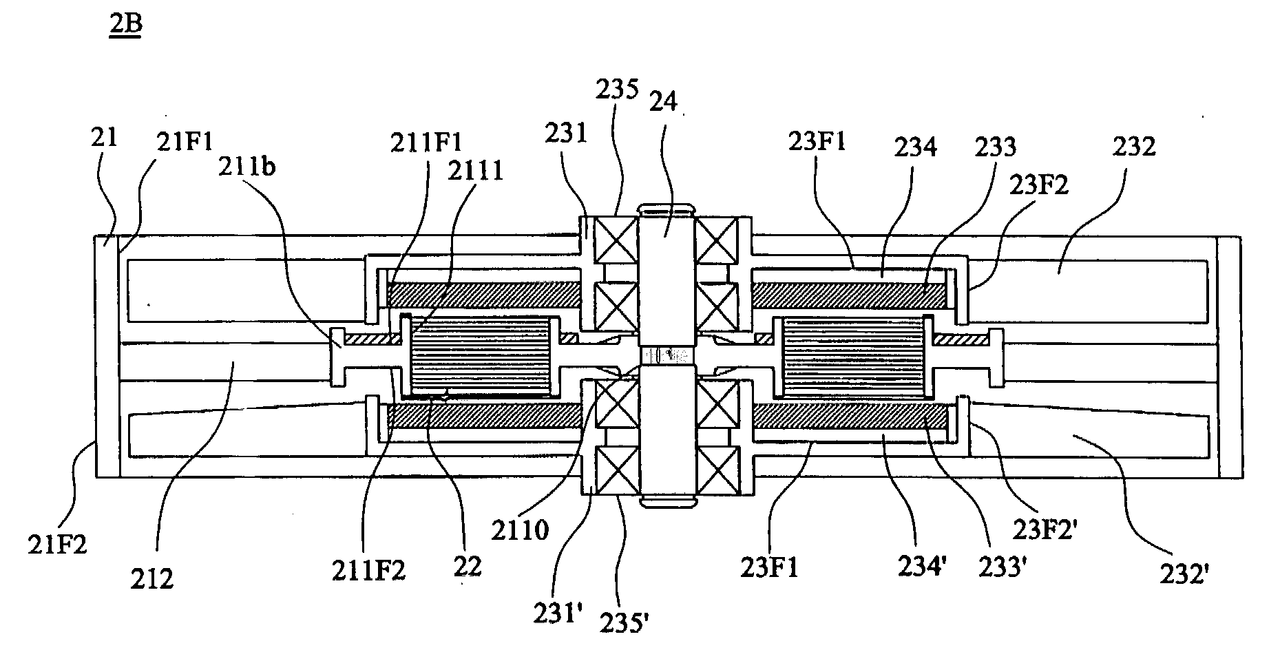
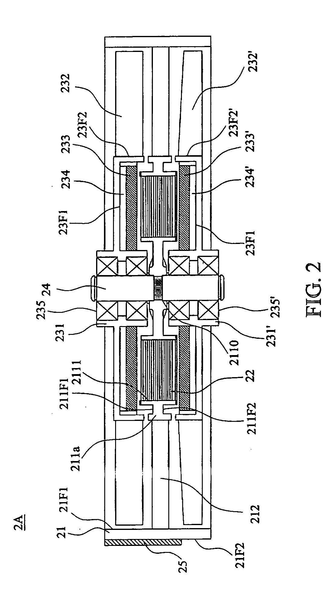
[0022] In FIG. 2, a fan 2A of the first embodiment of the invention comprises a frame 21, a base 211a disposed in the outer frame 21, a plurality of connecting portions 212, a stator 22, a first rotor 31, a second rotor 31′, a plurality of bearings 235 and 235′, a shaft 24 and a controller 25. In this embodiment, the connecting portions 212, such as ribs or stationary blades, are securely disposed between the base 211a and the inner surface 21F1 of the frame 21. The base 211a comprises a first surface 211F1, a second surface 211F2, a centrally arranged through hole 2110 to telescope the shaft 24, and a plurality of hollow penetrating portions 2111 protruding from the...


PUM


Abstract

A three-phase opposite rotating motor of a fan comprises a stator having a three-phase coil set without a core, a first rotor and a second rotor. The number of the poles of the first rotor is unequal to the number of the poles of the second rotor. The ratio of the number of solenoids of the three-phase coil set and the number of the first poles of the first rotor is 3:4, and the ratio of the number of solenoids of the three-phase coil set and the number of the second poles of the second rotor is 3:2, to ensure the motor works normally in an opposite rotating operation.

Description

BACKGROUND OF THE INVENTION [0001] 1. Field of the Invention [0002] The invention relates to an opposite rotating motor and an opposite rotating fan, and in particular to a three-phase opposite rotating motor having a single stator and two rotors and a three-phase opposite rotating fan having thereof. [0003] 2. Description of the Related Art [0004] A conventional motor used in an axial fan comprises a single stator and a single rotor. To increase the output airflow or to prevent the primary fan from malfunctioning, it is essential that an auxiliary fan be disposed in series next to the primary fan. In fact, the primary and auxiliary fans are two independent fans, i.e. each fan has its own power supply system. However, these fans occupy a larger space and require a lengthy installation process, and the auxiliary fan increases the manufacturing cost. Further, it is possible that the resistance between the primary and auxiliary fans may be increased, so that the airflow cannot be effic...

Claims


Application Information

Patent Timeline
IPC IPC(8): H02K16/02H02K21/12H02K1/22F04B17/00H02K16/00
CPCF04D19/007H02K21/24H02K16/02F04D25/0653
Inventor CHUANG, KUN-FUCHANG, SHUN-CHENHUANG, SHIH-MINGHUANG, WEN-SHI
Owner DELTA ELECTRONICS INC
Why Eureka
Try Eureka