Low noise multiphase charge pump and control method thereof

Active Publication Date: 2007-07-05
RICHTEK TECH
View PDF3 Cites 10 Cited by
  • Summary
  • Abstract
  • Description
  • Claims
  • Application Information

AI Technical Summary

Benefits of technology

[0004]An object of the present invention is to provide a control method to reduce the current ripple and the voltage ripple of a charge pump.
[0005]Another object of the present invention is to provide a low noise multiphase charge pump.
[0006]In a charge pump having a plurality of capacitors and a plurality of switches configured as a network, according to the present invention, the pl

Problems solved by technology

Hence, this charge pump has huge current ripple.
Since the voltage ripple is proportional to the current ripple, the c

Method used


Image

  • Low noise multiphase charge pump and control method thereof
  • Low noise multiphase charge pump and control method thereof
  • Low noise multiphase charge pump and control method thereof

Examples


Embodiment Construction

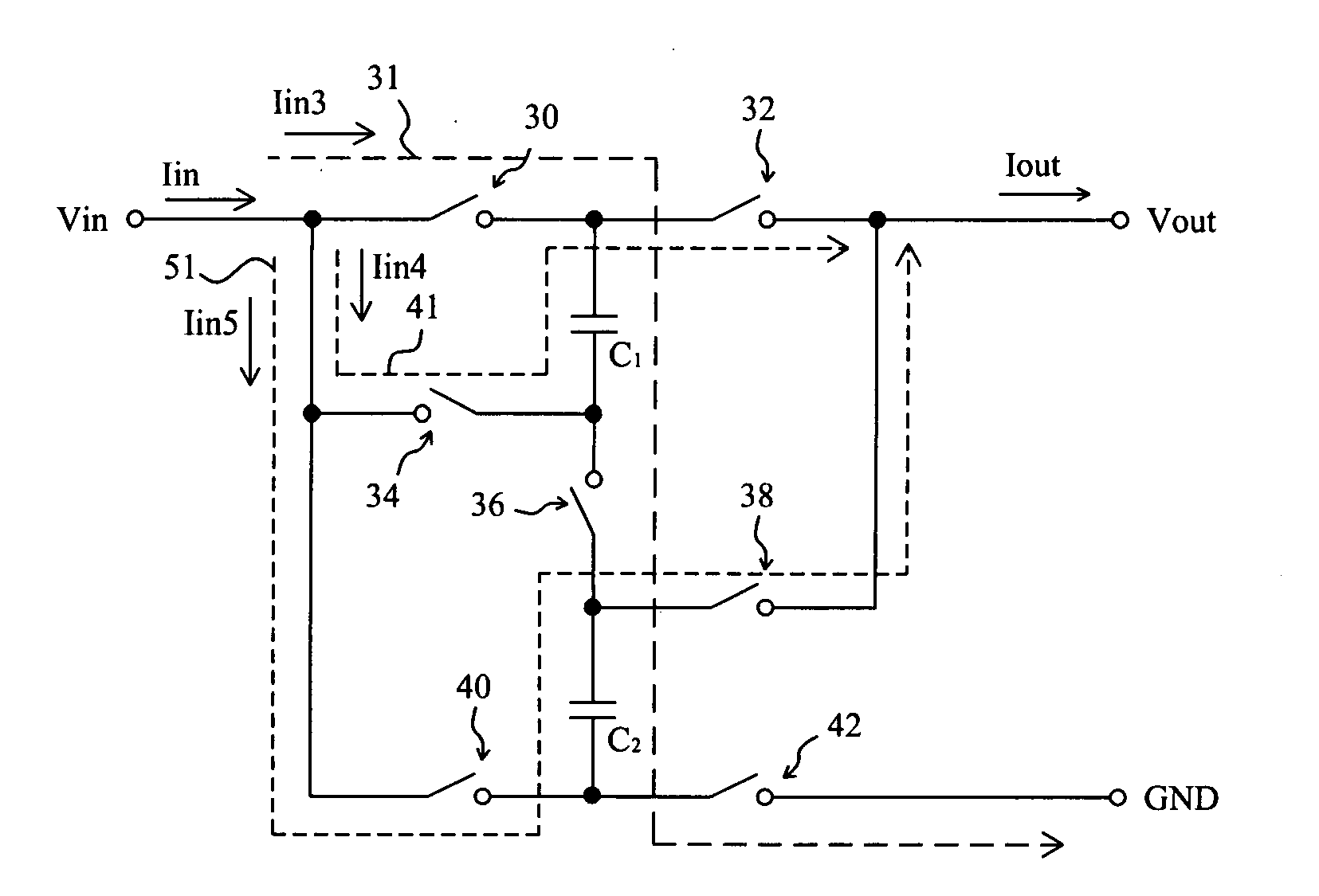
[0014]FIG. 3 shows a 1.5x mode multiphase charge pump according to the present invention, in which two capacitors C1 and C2 have a same capacitance C, and the difference between the maximum voltage and the minimum voltage on the capacitors C1 and C2 is ΔV2. When switches 30, 36 and 42 turn on and the others turn off, a charging path 31 is established and the charge pump operates in a charging phase, by which the capacitors C1 and C2 are coupled in series and charged. Let the charging time to be T3, therefore the charging current Iin3 will be C×ΔV2 / T3. When switches 32 and 34 turn on and the others turn off, a discharging path 41 is established and the charge pump operates in a first discharging phase, by which the capacitor C1 is discharged. Let the discharging time of this phase to be T4, therefore the discharging current Iin4 of this phase will be C×ΔV2 / T4. Then, the charge pump is switched to another discharging phase by turning on the switches 38 and 40 and turning off the other...


PUM


Abstract

A low noise multiphase charge pump comprises a plurality of capacitors and a plurality of switches configured as a network, the switches are so switched that the charge pump operates in at least three phases by turns, and the operational durations and the operational currents of the phases are preferably balanced, so as to reduce the noise of the charge pump.

Description

FIELD OF THE INVENTION[0001]The present invention is related generally to switching power supplies, and more particularly, to a charge pump switching power supply with smaller current and voltage ripples.BACKGROUND OF THE INVENTION[0002]Current electronic circuits often need more than one direct-current (DC) power supply, and therefore various systems are designed for power conversion, for example charge pumps. A conventional charge pump is switched between a charging phase and a discharging phase so as to operate in two phases, i.e., the charging phase and the discharging phase by turns. For example, in a 1.5x mode charge pump as shown in FIG. 1, two capacitors C1 and C2 have a same capacitance C, and the difference between the maximum voltage and the minimum voltage on the capacitors C1 and C2 is ΔV1. This charge pump operates in a charging phase when switches 10, 16 and 22 turn on and the others turn off, in which a charging path 11 is established to charge the serially coupled c...

Claims


Application Information

Patent Timeline
IPC IPC(8): G05F1/10
CPCH02M3/07
Inventor LIN, SHUI-MUKUNG, NIEN-HUICHEN, JIEN-SHENGHUANG, TSUNG-WEI
Owner RICHTEK TECH
Why Eureka
Try Eureka