
Determining optimal positioning of ophthalmic devices by use of image processing and autofocusing techniques

a technology of image processing and autofocusing, applied in the field of determining the optimal positioning of ophthalmic devices, can solve the problems of most time-consuming portions of the procedure, and achieve the effect of high frequency content and highest sharpness function

Active Publication Date: 2007-07-05
ALCON INC
View PDF4 Cites 24 Cited by
  • Summary
  • Abstract
  • Description
  • Claims
  • Application Information

AI Technical Summary

Benefits of technology

[0009]Embodiments of the present invention provide a system and method operable to position an ophthalmic device relative to an eye that substantially addresses the above identified needs as well as other needs. One embodiment provides a method which first obtains a series of images of an eye. In the series of images, the distance between the ophthalmic device and the eye is varied while the region of the eye image remains substantially the same. The images are then processed to determine a high frequency content or sharpness function associated with each image. By comparing the high frequency content associated with each image, the image having the largest amount of high frequency content or highest sharpness function is identified. The high frequency content or sharpness function varies with the focus of the image. An optimally focused image will have the largest amount of high frequency content or highest sharpness function. By identifying the image associated with the highest frequency content or sharpness function from the series of images, the relative position or distance between the eye and the ophthalmic device having the largest amount of high frequency content (i.e., optimally focused) is identified. This distance may be used to position the ophthalmic device relative to the patient's eye.

Problems solved by technology

One of the most time consuming portions of the procedure is the set up and positioning of the laser.

Method used


Image

  • Determining optimal positioning of ophthalmic devices by use of image processing and autofocusing techniques
  • Determining optimal positioning of ophthalmic devices by use of image processing and autofocusing techniques
  • Determining optimal positioning of ophthalmic devices by use of image processing and autofocusing techniques

Examples


Embodiment Construction

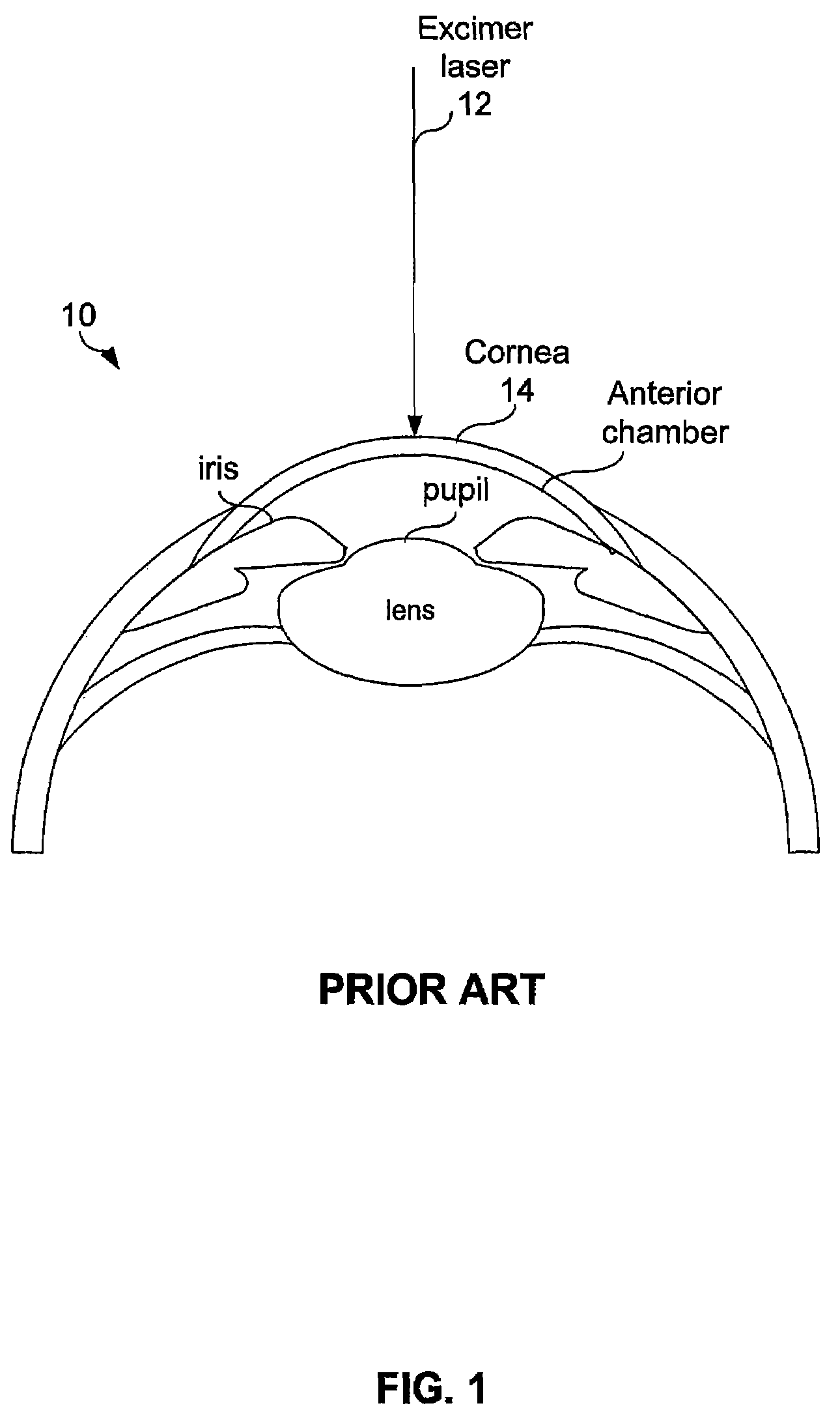
[0022]Preferred embodiments of the present invention are illustrated in the FIGs., like numerals being used to refer to like and corresponding parts of the various drawings.

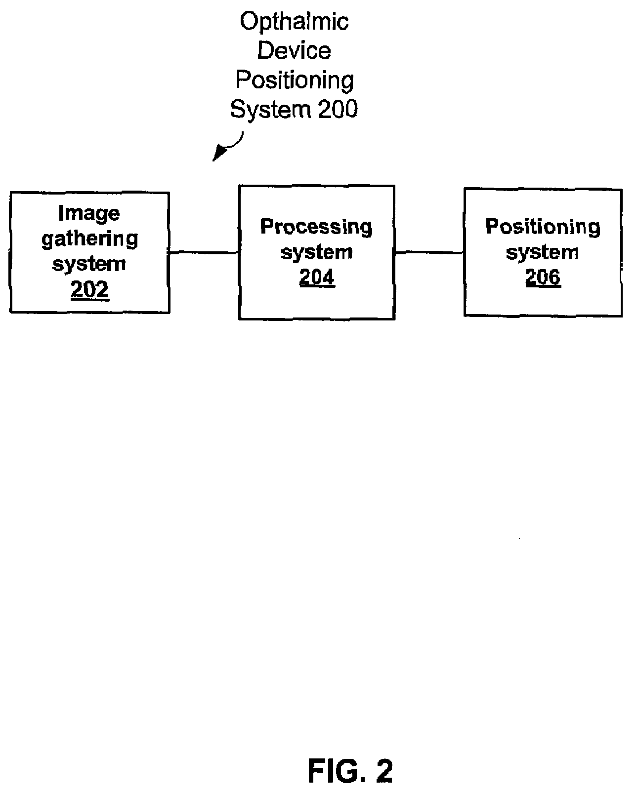
[0023]FIG. 2 provides an ophthalmic device positioning system 200. Ophthalmic device positioning system 200 includes an image gathering system 202, a processing system 204, and a positioning system 206. The image gathering system 202 may be a camera or a video device operable to gather a series of images of the eye. Image gathering system 202 is operable to record relative distance between the image gathering system 202 and the eye where the image is gathered. The processing system 204, as will be discussed in further detail, receives the images gathered and performs a sharpness function on each of the gathered images.

[0024]The processing system 204 may be a single processing device or a plurality of processing devices. Such a processing device may be a microprocessor, micro-controller, digital signal processor, ...


PUM


Abstract

A system or method of positioning an ophthalmic device relative to an eye is provided. The method first obtains a series of images of an eye. In these series of images, the distance between the ophthalmic device and the eye is varied while the region of the eye image remains substantially the same. It is possible then to process these images to determine the high frequency content associated with each image. By comparing the high frequency content associated with each image, it is possible to determine which image has the largest amount of high frequency content. The high frequency content is maximized when the image is the sharpest. An optimally focused image will have the largest amount of high frequency content. By examining the high frequency content associate with the series of images is impossible to adjust the relative position and distance between the eye and the ophthalmic device to the distance associated with the image having the largest amount of high frequency content (i.e., optimally focused).

Description

CROSS-REFERENCE TO RELATED APPLICATIONS[0001]This application claims priority under 35 U.S.C. §119 to U.S. Provisional Patent Application No. 60 / 755,556, filed Dec. 31, 2005, the entire contents of which are incorporated herein by reference.TECHNICAL FIELD OF THE INVENTION[0002]The present invention relates generally to ophthalmic devices, and more particularly, to a system and method for determining optimal positioning of ophthalmic devices.BACKGROUND OF THE INVENTION[0003]Positioning an ophthalmic device a known distance from an eye being examined is typically of great importance. In many devices one reason for this precise positioning is to have features of the eye in clear focus—potentially for subsequent interaction with the image by an operator or software. Other reasons include the need to have a laser beam come to focus at the correct plane with respect to the eye (for example in an excimer laser system) or to have the eye optimally positioned for subsequent measurement of t...

Claims


Application Information

Patent Timeline
Patent Type & Authority Applications(United States)
IPC IPC(8): A61B3/14
CPCA61B3/0075A61B3/0083A61B3/10G06T2207/30041A61F9/00802A61F2009/00872G06T7/0069A61B3/145G06T7/571
Inventor CAMPIN, JOHN A.BOWES, JOHN J.
Owner ALCON INC
Learn More