Optical Apparatus and Optical Measurement Method

a technology of optical instruments and optical measurement methods, applied in the field of optical instruments, can solve problems such as incongruity and non-uniform direction, source may produce scattered light without uniformity, and produce bad image quality, so as to improve image sensing quality

Inactive Publication Date: 2007-07-05
KUO PENG CHIA
View PDF1 Cites 3 Cited by
  • Summary
  • Abstract
  • Description
  • Claims
  • Application Information

AI Technical Summary

Benefits of technology

[0005]Accordingly, the object of the present invention is to provide an optical

Problems solved by technology

The scattered light emitted by the point light source or the line light source would cause non-uniformity and inconsistent directions.
The bad image quality is produced when the point light source or the line light source is applied to the image sensing system.
However, the point light source may produce a scattered light without uniformity

Method used


Image

  • Optical Apparatus and Optical Measurement Method
  • Optical Apparatus and Optical Measurement Method
  • Optical Apparatus and Optical Measurement Method

Examples


Embodiment Construction

[0015]To make it easier for understanding the objective of the invention, its innovative features and performance, a detailed description and technical characteristics of the power line communication system are described together with the drawings as follows.

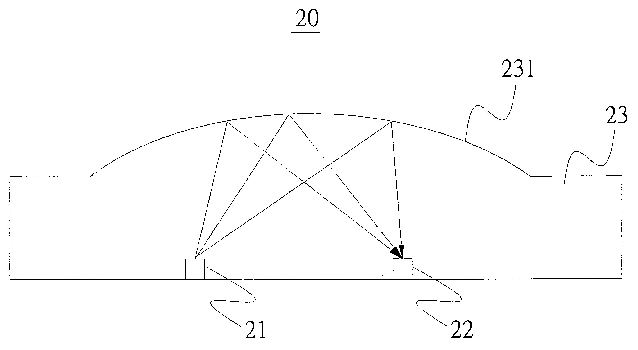
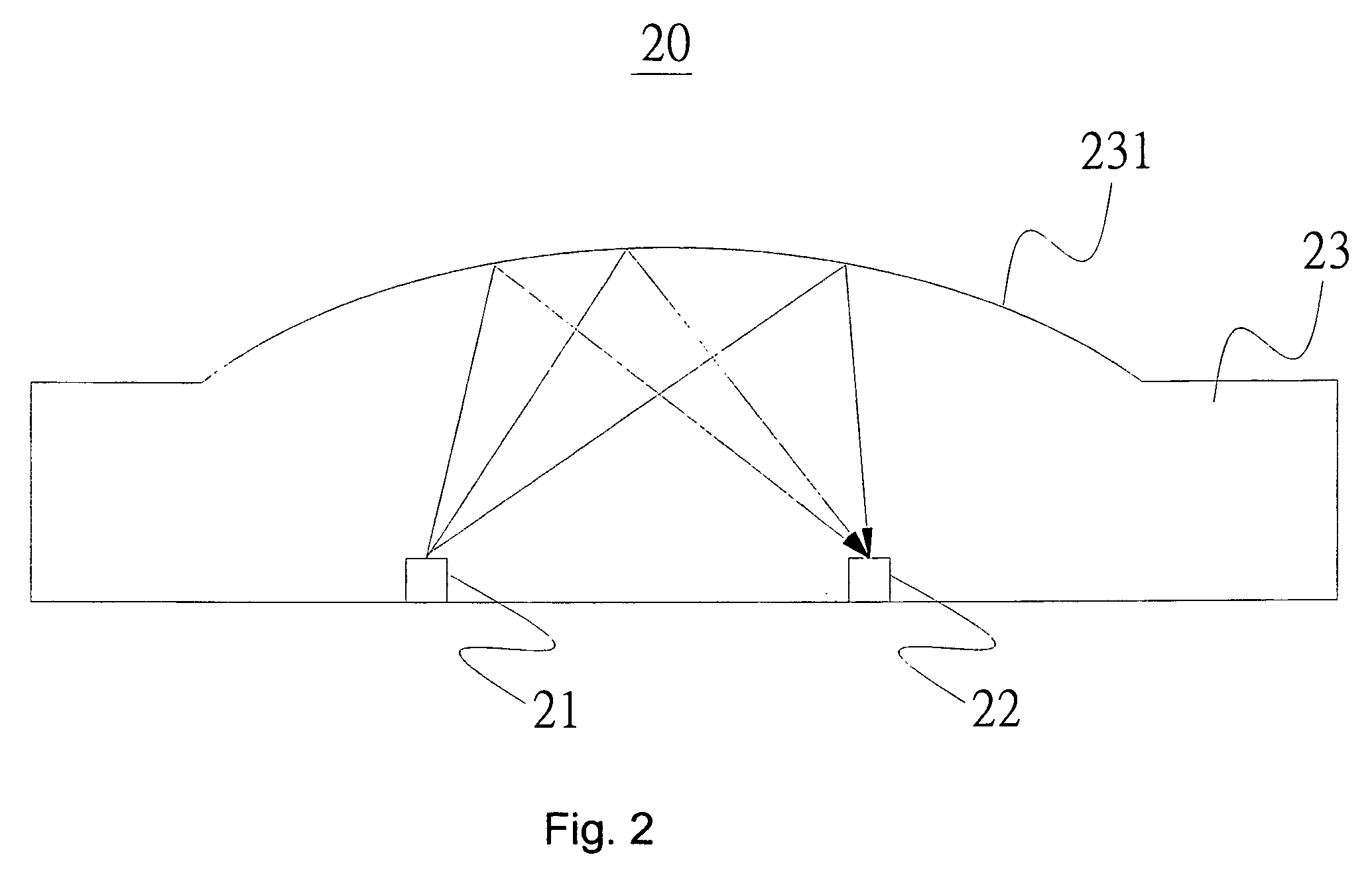
[0016]Referring to FIG. 2, a schematic diagram illustrates an optical apparatus according to an embodiment of the present invention. The optical apparatus 20 comprises a light source 21, an optical sensing device 22 and an optical element 23. The optical sensing device 22 and the light source 21 are set at the same side. The optical element 23 has a reflector 231. The reflector 231 is an arc and a light emitted by the light source 21 can be reflected by the reflector 231 to the optical sensing device 22. The light source 21 is a light emitting diode (LED), the optical sensing device 22 is a complementary metal oxide semiconductor (CMOS) element or a charge coupled device (CCD), the optical element 23 is a prism and the circular ...


PUM


Abstract

An optical apparatus comprises a light source, an optical sensing device and an optical element. The optical sensing device and the optical element are set at the same side. The optical element includes a reflector which is an arc. A light emitted by the light source can be reflected by the reflector of the optical element to the optical sensing device.

Description

FIELD OF THE INVENTION[0001]The present invention relates to an optical apparatus and, more particularly, to integrate an optical element having a reflector with an arc for the optical apparatus and an optical measurement method.BACKGROUND OF THE INVENTION[0002]Currently, a light emitting apparatus applied to the optical system often uses a point light source or a line light source especially for the fingerprint recognition apparatus. The scattered light emitted by the point light source or the line light source would cause non-uniformity and inconsistent directions. The bad image quality is produced when the point light source or the line light source is applied to the image sensing system. Referring to FIG. 1, a schematic diagram illustrates a conventional image sensing system. The image sensing system 10 comprises a point light source 11, a prism 12, a convex lens 13 and an image sensing device 14. A beam 111 emitted by the point light source 111 is reflected by the prism 12 to t...

Claims


Application Information

Patent Timeline
IPC IPC(8): G06K9/74
CPCG06K9/00046G06V40/1324
Inventor KUO, PENG CHIA
Owner KUO PENG CHIA
Why Eureka
Try Eureka