
Motor overcurrent protection device

a protection device and motor technology, applied in circuit arrangements, emergency protection arrangements for limiting excess voltage/current, lighting and heating apparatus, etc., can solve the problems of increasing the cost of the motor overcurrent protection device, increasing the cost, and b>100/b> tending to overheat and damage, etc., to achieve accurate control of the rotational speed of the motor

Inactive Publication Date: 2007-07-05
TRANMAX MACHINERY +1
View PDF4 Cites 2 Cited by
  • Summary
  • Abstract
  • Description
  • Claims
  • Application Information

AI Technical Summary

Benefits of technology

[0012]It is therefore a primary object of the present invention to provide a motor overcurrent protection device. The motor overcurrent protection device can precisely judge abnormal operation of a motor and real-time react to protect the motor. In addition, the motor overcurrent protection device of the present invention can accurately control the rotational speed of the motor and distinguish whether the motor cannot operate in the instant of activating the motor or the motor operates at too low speed after activated. Therefore, the rotational speed can be real-time adjusted to protect the motor. Also, this helps in judging the cause of the failure for quickly removing the failure.
[0015]In the motor overcurrent protection device of the present invention, the sensing unit is omissible. A magnetic block and a Hall device inside a brushless motor can be directly used instead of the sensing unit. This can achieve the same sensing effect.

Problems solved by technology

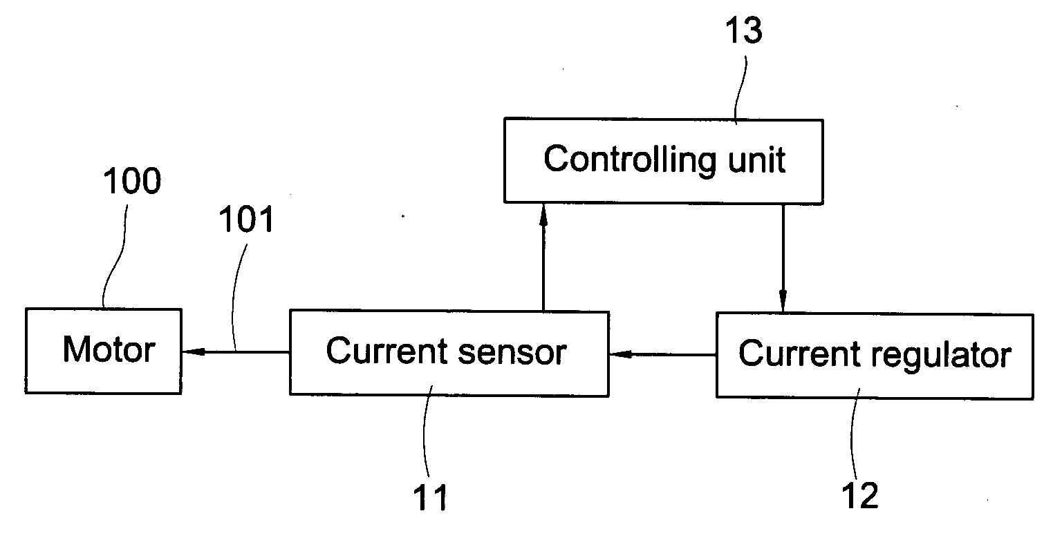
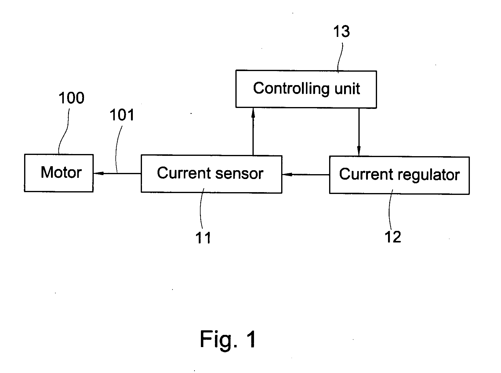
Consequently, in condition of high current, the motor 100 tends to overheat and damage.
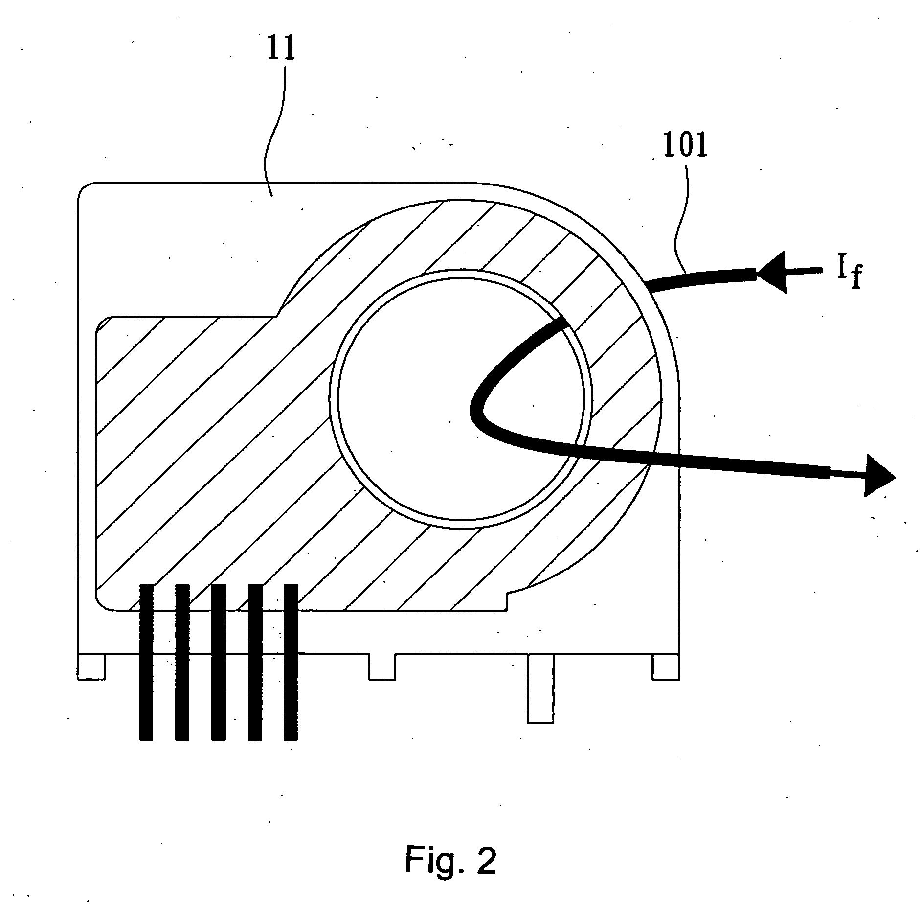
The current sensor 11 leads to increment of the cost for the motor overcurrent protection device.
This not only increases the cost, but also complicates the circuit and enlarges the volume of the device.
However, the conventional device cannot tell whether the motor 100 malfunctions immediately after activated or after having operated for a certain period.
The conventional device is unable to distinguish these two situations from each other so that a repairman can hardly quickly remove the failures.
Therefore, the cost is still relatively high and the efficiency and precision still cannot be promoted.

Method used


Image

  • Motor overcurrent protection device
  • Motor overcurrent protection device
  • Motor overcurrent protection device

Examples


Embodiment Construction

[0021]Please refer to FIG. 3. The motor overcurrent protection device of the present invention is connectable to a motor 200. The motor 200 has a rotary shaft 201 and a controlling port 202 for controlling the motor 200. The motor overcurrent protection device includes a sensing unit 30, a driving unit 40 and a controlling unit 50.

[0022]The sensing unit 30 includes a magnetic block 31 and a Hall device 32. The magnetic block 31 is arranged on a circumference of the rotary shaft 201. The Hall device 32 is positioned beside the rotary shaft 201. The magnetic block 31 is rotatable along with the rotary shaft 201 to be instantaneously aligned with the Hall device 32.

[0023]The driving unit 40 is electrically connected with the controlling port 202 of the motor 200. In this embodiment, the driving unit 40 adjusts the rotational speed of the motor 200 by way of regulating the current. The driving unit 40 is a circuit composed of transistor Q1 made by the American manufacturer International...


PUM


Abstract

A motor overcurrent protection device connectable to a motor. The motor has a rotary shaft and a controlling port. The motor overcurrent protection device includes a sensing unit, a driving unit and a controlling unit. The sensing unit includes a magnetic block arranged on a circumference of the rotary shaft and a Hall device positioned beside the rotary shaft. The magnetic block is rotatable along with the rotary shaft to be instantaneously aligned with the Hall device. The driving unit is electrically connected with the controlling port of the motor. The controlling unit is electrically connected with the sensing unit and the driving unit. When the motor operates, each time the magnetic block is aligned with the Hall device, the Hall device outputs a pulse signal which is stored in the controller of the controlling unit. All the pulse signals are summed up in a preset sensing time of the controller. In the case that the sum does not exceed a standard rotational speed value, the controlling unit via the driving unit will stop the motor from operating so as to protect the motor from malfunctioning due to rising of current.

Description

BACKGROUND OF THE INVENTION[0001]The present invention is related to a motor circuit device, and more particularly to a motor overcurrent protection device.[0002]FIGS. 1 and 2 show a conventional motor overcurrent protection device connected to a motor 100. The motor 100 has a controlling lead 101. The motor overcurrent protection unit includes a current sensor 11, a current regulator 12 and a controlling unit 13.[0003]The current sensor 11 is looped with the controlling lead 101 for sensing the working current IF of the motor 100. As shown in FIG. 2, the current sensor 11 is a Hall effect current sensor made by an American manufacturer TAMURA Company under Model No. L08PO50D15.[0004]The current regulator 12 is serially connected with the current sensor 11 via the controlling lead 101 for regulating the working current IF. In general, the current regulator 12 is a circuit made by an American manufacturer International Rectifier Company under Model No. IRF640.[0005]The controlling un...

Claims


Application Information

Patent Timeline
Patent Type & Authority Applications(United States)
IPC IPC(8): H02H7/08
CPCH02H7/093
Inventor WANG, FRANKCHEN, PAO-HSIANG
Owner TRANMAX MACHINERY
Learn More