Control apparatus for vehicular drive system, vehicle provided with the control apparatus, and method for controlling vehicular drive system

a control apparatus and vehicular drive technology, applied in electric propulsion mounting, transportation and packaging, gearing, etc., can solve the problems of increasing the amount of engine speed racing, affecting the shifting action of the step-variable transmission portion, and affecting the transmission speed of the engine. , to achieve the effect of adequately reducing the influence of the engine torque variation on the shifting action of the step-variable transmission portion, and reducing the torque capacity of the input clutch

Inactive Publication Date: 2007-07-05
TOYOTA JIDOSHA KK
View PDF4 Cites 36 Cited by
  • Summary
  • Abstract
  • Description
  • Claims
  • Application Information

AI Technical Summary

Benefits of technology

[0027] In the inventions according to claims 11, 22 and 33, the input clutch is not used to effect the shifting action of the step-variable transmission portion. In this case, the step-variable transmission portion is shifted by a releasing action of a coupling device and an engaging action of another coupling device, so that the influence of the engine torque variation on the shifting action of the step-variable transmission portion is adequately reduced.
[0028] Preferably, the power transmitting path between the engine and the step-variable transmission portion is not provided with a fluid-operated power transmitting device, so that the engine is connected to the step-variable transmission portion through the input clutch. In this case, the reduction of the torque capacity of the input clutch by the input-clutch control means is more effective to educe the shifting shock of the step-variable transmission portion during its shifting action.

Problems solved by technology

However, a change of the engaging pressures may deteriorate a transfer of a torque from the frictional coupling device in its releasing action to the frictional coupling device in its engaging action.
If the engaging pressures are not changed to prevent a risk of the deterioration of the above-indicated torque transfer, or cannot be rapidly changed in response to the torque variation, the amount of the engine speed racing tends to be increased, or the step-variable automatic transmission tends to suffer from a so-called “tie-up” phenomenon in which the output torque is temporarily reduced, whereby the step-variable automatic transmission has a risk of shifting shock.
However, there is not available a power transmitting mechanism which has advantages of these two power transmitting devices.
Accordingly, the required size of the second electric motor operated by the electric energy received from the first electric motor is increased, whereby the hybrid vehicle drive system must be undesirably large-sized.
Alternatively, a portion of the output of the engine is once converted into an electric energy which is then converted into a mechanical energy to be transmitted to the drive wheels, so that hybrid vehicle drive system has a risk of deterioration of the fuel economy depending upon the running condition of the vehicle, for example, during a high-speed running of the vehicle.
A similar problem is encountered where the above-indicated power distributing mechanism is constituted by a transmission the speed ratio of which is electrically variable, for example, a continuously variable transmission which is so-called “an electric CVT”.
Where the hybrid vehicle drive system including the differential mechanism and the step-variable automatic transmission is not provided with a fluid-operated power transmitting device, the drive system has a risk of a shifting shock which takes place due to a variation of the engine torque during a shifting action of the step-variable automatic transmission.
This vehicular drive system also has a risk of a shifting shock which takes place due to the engine torque variation during the shifting action of the step-variable automatic transmission.

Method used


Image

  • Control apparatus for vehicular drive system, vehicle provided with the control apparatus, and method for controlling vehicular drive system
  • Control apparatus for vehicular drive system, vehicle provided with the control apparatus, and method for controlling vehicular drive system
  • Control apparatus for vehicular drive system, vehicle provided with the control apparatus, and method for controlling vehicular drive system

Examples


embodiment 1

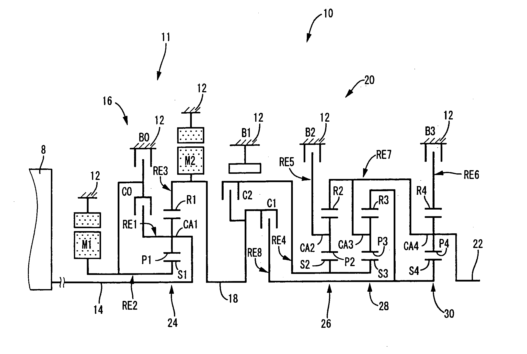
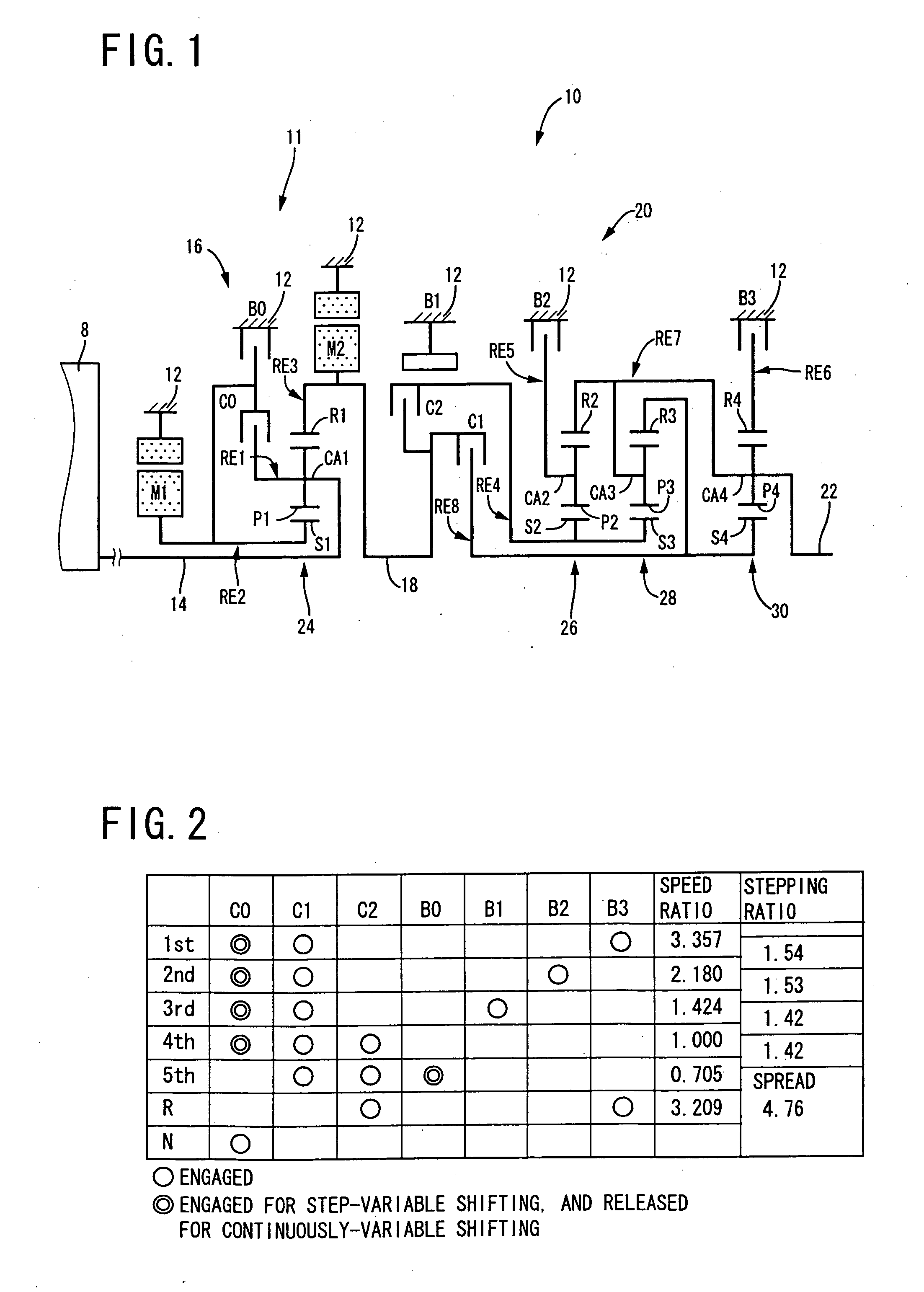
[0056] Referring to the schematic view of FIG. 1, there is shown a transmission mechanism 10 constituting a part of a drive system for a hybrid vehicle, which drive system is controlled by a control apparatus according to one embodiment of this invention. In FIG. 1, the transmission mechanism 10 includes: an input rotary member in the form of an input shaft 14; a differential portion 11 connected to the input shaft 14 either directly, or indirectly via a pulsation absorbing damper (vibration damping device) not shown; a step-variable transmission portion functioning as a step-variable type transmission in the form of an automatic transmission portion 20 disposed between the differential portion 11 and drive wheels 38 of the vehicle, and connected in series via a power transmitting member 18 (power transmitting shaft) to the transmission portion 11 and the drive wheels 38; and an output rotary member in the form of an output shaft 22 connected to the automatic transmission portion 20...

embodiment 2

[0220]FIG. 15 is a schematic view for explaining an arrangement of a transmission mechanism 70 in another embodiment of this invention, and FIG. 16 a table indicating a relationship between the gear positions of the transmission mechanism 70 and different combinations of engaged states of the hydraulically operated frictional coupling devices for respectively establishing those gear positions, while FIG. 17 is a collinear chart for explaining a shifting operation of the transmission mechanism 70.

[0221] The transmission mechanism 70 includes the differential portion 11 having the first electric motor M1, power distributing mechanism 16 and second electric motor M2, as in the preceding embodiment. The transmission mechanism 70 further includes an automatic transmission portion 72 having three forward drive positions. The automatic transmission portion 72 is disposed between the differential portion 11 and the output shaft 22 and is connected in series to the differential portion 11 a...

embodiment 3

[0229]FIG. 18 shows an example of a seesaw switch 44 (hereinafter referred to as “switch 44”) functioning as a shifting-state selecting device manually operable to select the differential state (non-locked state) and or non-differential state (locked state) of the power distributing mechanism 16, that is, to select the continuously-variable shifting state or step-variable shifting state of the transmission mechanism 10. This switch 44 permits the user to select the desired shifting state during running of the vehicle. The switch 44 has a continuously-variable-shifting running button labeled “STEP-VARIABLE” for running of the vehicle in the continuously-variable shifting state, and a step-variable-shifting running button labeled “CONTINUOUSLY-VARIABLE” for running of the vehicle in the step-variable shifting state. When the continuously-variable-shifting running button is depressed by the user, the switch 44 is placed in a continuously-variable shifting position for selecting the con...


PUM


Abstract

A control apparatus for a vehicular drive system provided with a step-variable transmission portion operable to transmit an output of an engine to a drive wheel of a vehicle and functioning as a step-variable transmission, and an input clutch operable to permit and inhibit an input of a drive force from the engine to the step-variable transmission portion, the control apparatus including an input-clutch control portion operable to reduce a torque capacity of said input clutch, during a shifting action of the step-variable transmission portion, for limiting a torque to be transmitted to the step-variable transmission portion, to a value not larger than a predetermined value.

Description

[0001] The present application is based on Japanese Patent Application No. 2005-182400. TECHNICAL FIELD [0002] 1. Field of the Invention [0003] The present invention relates to a control apparatus for a vehicular drive system a step-variable automatic transmission, and more particularly to techniques for shifting shock of the vehicular drive system. [0004] 2. Discussion of Prior Art [0005] There is generally well known a step-variable automatic transmission arranged to perform clutch-to-clutch shifting actions each effected by a releasing action of a frictional coupling device and an engaging action of another frictional coupling device, or to perform one-way clutch shifting actions each effected by using a one-way clutch. In the clutch-to-clutch shifting action in this type of step-variable automatic transmission, for example, a so-called “overlap control” is effected to control an amount of overlap of an engaging torque of the frictional coupling device in its releasing action and...

Claims


Application Information

Patent Timeline
Patent Type & Authority Applications(United States)
IPC IPC(8): B60W10/00B60K6/445B60K6/543B60K6/547B60L50/16B60W10/02B60W10/10B60W20/00F16D48/02F16H59/14F16H59/68F16H61/06F16H61/68F16H61/684F16H61/686F16H63/50
CPCB60K1/02Y10T477/638B60K6/40B60K6/445B60K6/547B60W10/06B60W10/115B60W20/00B60W30/19B60W2710/025F16H2037/0873F16H2200/0043F16H2200/0047F16H2200/201F16H2200/2012F16H2200/2046F16H2200/2048Y02T10/6239Y10T477/641Y10T477/26Y10T477/23Y10T477/78B60K6/365F16H3/66F16H2200/2007Y02T10/62B60W20/10
Inventor TABATA, ATSUSHITAGA, YUTAKAINOUE, YUJIKAMADA, ATSUSHI
Owner TOYOTA JIDOSHA KK
Why Eureka
Try Eureka