Display device

a display device and rear cover technology, applied in the field of display devices, can solve the problems of inability to properly mount the lcd device, easy etc., and achieve the effect of minimizing the deformation of the rear cover of the device during assembly

Inactive Publication Date: 2007-07-12
SAMSUNG ELECTRONICS CO LTD
View PDF4 Cites 20 Cited by
  • Summary
  • Abstract
  • Description
  • Claims
  • Application Information

AI Technical Summary

Benefits of technology

[0007] In accordance with the exemplary embodiments thereof disclosed herein, the present invention provid

Problems solved by technology

However, the rear cover may easily become deformed by pressure when the coupling parts are slidably eng

Method used


Image

  • Display device
  • Display device
  • Display device

Examples


first embodiment

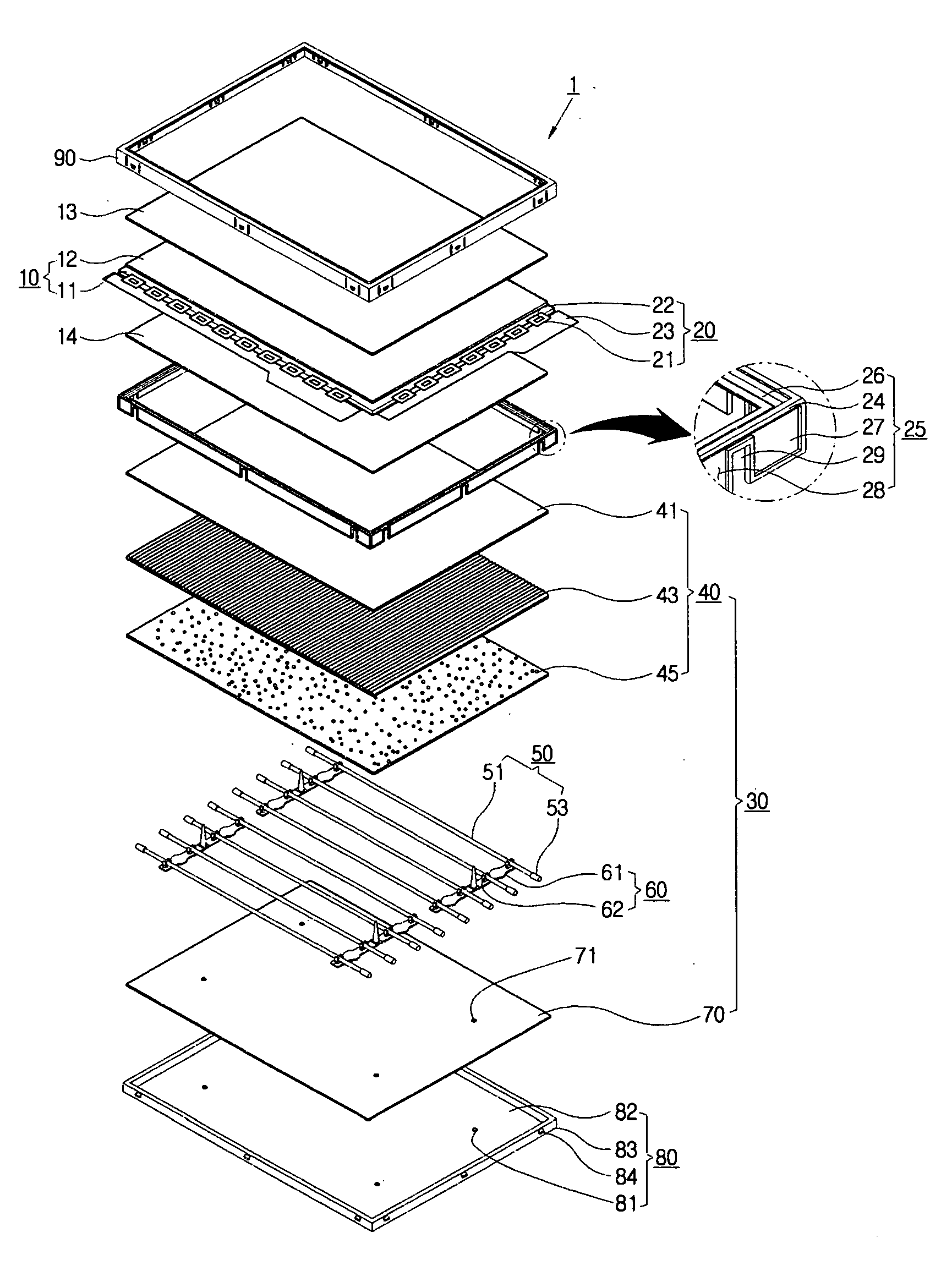
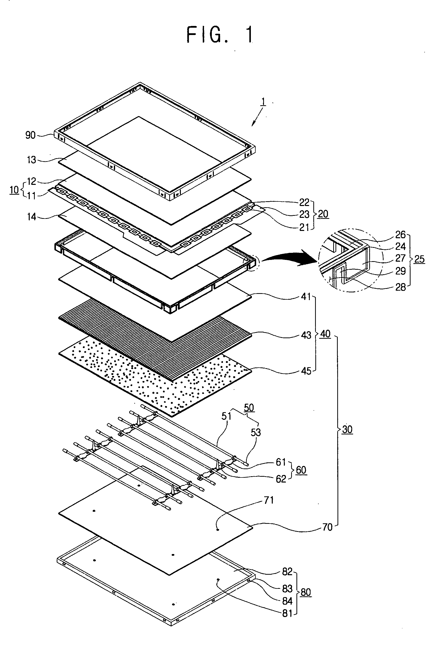
[0054] With the foregoing configuration in mind, a method for assembling the display device 1 according to the present invention of FIG. 1 is described below in conjunction with FIGS. 3 to 5B.

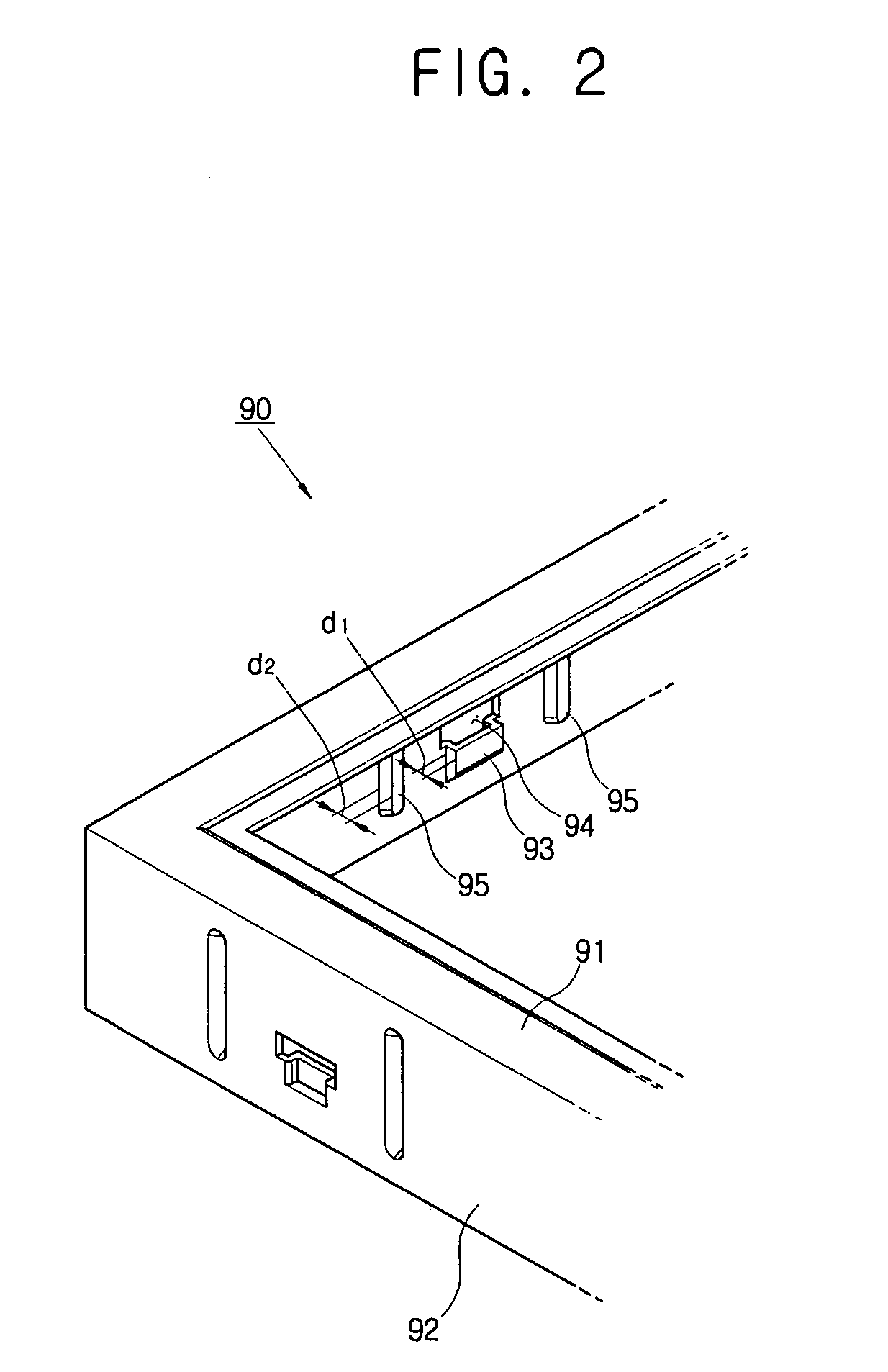
[0055] As illustrated in FIG. 3, the front cover 90 is pressed down over the mold frame 25 and rear cover 80. As discussed above, the distance from the rear ends of the elongated protrusions 95 to the bottom surface of the bottom plate 82 of the rear cover 80 is less than that from the front end of the front cover coupling part 93 to the bottom surface of the rear cover bottom plate 82. Thus, the rear ends of the elongated protrusions 95 contact the front cover lateral projection 24 first during the assembly of the front cover 90 onto the rear cover.

[0056] As illustrated in FIG. 4A, the inclined ramp face contacting surface “b” on the rear end of the elongated protrusion 95 slidably contacts the inclined ramp face contact surface “a” of the front edge of the lateral projection 24. As illustrat...

second embodiment

[0060] Following is a detailed description of the assembly of display device. As shown in FIG. 6A, when the front cover 90 is initially pressed down onto the rear cover 80, the front cover lateral part 92 slidably contacts the mold frame lateral projection 24. As illustrated in FIGS. 6A and 6C, the lateral distance d4 from the rear cover lateral wall 83 to the outer end of the projection 24 is larger than the lateral distance d5 (FIG. 6C), and accordingly, the front cover coupling parts 93 are disposed concentrically with respect to the rear cover coupling parts 84 and spaced laterally apart from them at a selected distance d3, as illustrated in the detail breakout view of FIG. 6C. That is, the front cover coupling parts 93 are disposed concentrically about and spaced apart from the rear cover coupling parts 84 by the mold frame lateral projection 24 during the assembly of the front cover to the rear cover. Thus, the rear cover 80 receives less pressure while being coupled with the ...

third embodiment

[0062]FIGS. 7A to 7D respectively illustrate a third exemplary embodiment of a display device in accordance with the present invention. With reference to these figures, a front cover coupling part 93 of the third embodiment protrudes laterally outward from a front cover lateral part 92. As illustrated in FIGS. 7A and 7C, the sum of the lateral height d2 of an elongated inward protrusion 95 on an inner surface of the lateral part 92 of the front cover 90 and a lateral height d4 of a lateral projection 24 on the mold frame 25 from an outer surface of the lateral wall 83 of the rear cover 80 is greater than the lateral height d6 of a rear cover coupling part 84.

[0063] As illustrated in FIG. 7A, when the front cover 90 is pressed down over the mold frame 25 and rear cover 80, the protrusion 95 on the front cover slidably contacts the projection 24 first. As shown in FIGS. 7A and 7C, as the sum of the lateral height d2 of the inward protrusion 95 and the lateral height d4 of the lateral ...


PUM


Abstract

An LCD includes a liquid crystal panel, a backlight unit, a rear cover, a mold frame and a front cover that slides down over and couples with the rear cover to form a space within which the liquid crystal panel, mold frame and backlight unit are protectively enclosed. The front cover has a lateral part with a first coupling part and a feature for receiving a lateral projection on the mold frame. The rear cover has a mold frame lateral wall with a second coupling part adapted to slidably engage and couple with the first coupling part when the front cover is slid down on the rear cover, and the mold frame has a lateral projection that is received in the front cover receiving feature when the front and rear covers are fully assembled together. The foregoing features enable deformation of the lower cover to be minimized during assembly of the device.

Description

RELATED APPLICATIONS [0001] This application claims priority of Korean Patent Application No. 2006-0002433, filed Jan. 9, 2006, the entire disclosure of which is incorporated herein by reference. BACKGROUND [0002] The present invention relates to display devices, such as liquid crystal displays (LCDs) and more particularly, to display devices in which the deformation of a rear cover of the display is minimized during the assembly thereof. [0003] Increasingly, flat panel display devices, such as liquid crystal displays (LCDs), plasma display panels (PDPs) and organic light emitting diode (OLED) displays, are being adopted to replace larger, heavier and bulkier cathode ray tube (CRT) display devices. [0004] LCDs comprise a thin film transistor substrate, a color filter substrate and a layer of a liquid crystal material interposed between the two substrates to form a liquid crystal panel. Additionally, as the LCD does not itself emit light, it is typically provided with a “backlight” u...

Claims


Application Information

Patent Timeline
IPC IPC(8): A43B5/04A43B5/16
CPCG02F1/133308G02F1/133608G02F2201/465G02F2001/133322G02F2001/133317G02F1/133317G02F1/133322G02F1/1333
Inventor HYUN, MIN-GWANLEE, JEOUNG-GWENSON, JUN-HEESHIN, JIN-SOO
Owner SAMSUNG ELECTRONICS CO LTD
Why Eureka
Try Eureka