
Sectioning instrument

Active Publication Date: 2007-07-12
SAKURA FINETEK JAPAN
View PDF8 Cites 18 Cited by
  • Summary
  • Abstract
  • Description
  • Claims
  • Application Information

AI Technical Summary

Benefits of technology

[0022] According to the sectioning instrument according to the invention, since the cutter is provided to include the draw angle, a resistance in sectioning the embedded block can be restrained and the embedded block can be sliced by an accurate and uniform thickness and by an excellent cut face. At this occasion, the direction switching portion is provided to be proximate to the cut blade substantially in parallel with the direction of the cut blade of the cutter and therefore, the section fabricated by the cutter can firmly be mounted on the belt. On the other hand, the belt is reeled back in the direction of fabricating the section by the rear roller, that is, the feed direction of the feed mechanism. Therefore, the section fabricated by the cutter and carried by being brought into contact with the belt is carried in a state of being mounted on the belt without being cut by operating twist or the like by traveling of the belt. Further, the belt is not twisted even when the direction switching portion is provided to include the draw angle along with the cut blade by inclining the supply direction in which the belt travels from the supply roller to the direction switching portion by the angle substantially equal to the draw angle relative to the axis line orthogonal to the direction of the cut blade. Therefore, the belt can smoothly be made to travel from the supply roller to the direction switching portion, further, the direction switching portion to the rear roller.
[0026] According to the sectioning instrument according to the invention, since the cutter is provided to include the draw angle, the resistance in sectioning the embedded block can be restrained and the embedded block can be sliced by further accurate and uniform thickness and by an excellent cut face. On the other hand, the belt is reeled back in the direction of fabricating the section, that is, in the feed direction of the feed mechanism by the rear roller. Therefore, the section fabricated by the cutter and carried by being brought into contact with the belt is carried in a state of being mounted on the belt without being cut by operating twist or the like by traveling of the belt. At this occasion, since the direction switching portion is substantially in parallel with the cut blade of the cutter, the rear roller and the direction switching portion wound with the belt are not brought into a parallel positional relationship. However, since respective of the plurality of ring-like members forming the belt are provided with the different peripheral lengths in correspondence with the distance between the rear roller and the direction switching portion, the belt can be made to travel endlessly between the rear roller and the direction switching portion smoothly without being twisted.

Problems solved by technology

Therefore, in the related art, the step of taking out and carrying the fabricated section is carried out by manual operation since the section is extremely thin, and damage of curl, wrinkle, break or the like is liable to be brought about.
However, according to both of the apparatus and the method according to Patent Reference 1 and Patent Reference 2, it is necessary to adhere the tape or adhere the tape by an electrostatic force by pressing the tape to the surface of the embedded block before being sliced by the cutter, there is a concern of deforming the surface of the embedded block by pressing the tape to the embedded block.
That is, there poses a problem that the section cannot be fabricated accurately and by a uniform thickness by deforming the surface of the embedded block.
Further, there poses a problem that the surface of the embedded block cannot be observed in fabricating the section since the sample embedded in the embedded block is brought into a state of being covered always by the tape or the cutter by disposing the tape upward from the embedded block.

Method used


Image

  • Sectioning instrument
  • Sectioning instrument
  • Sectioning instrument

Examples


first embodiment

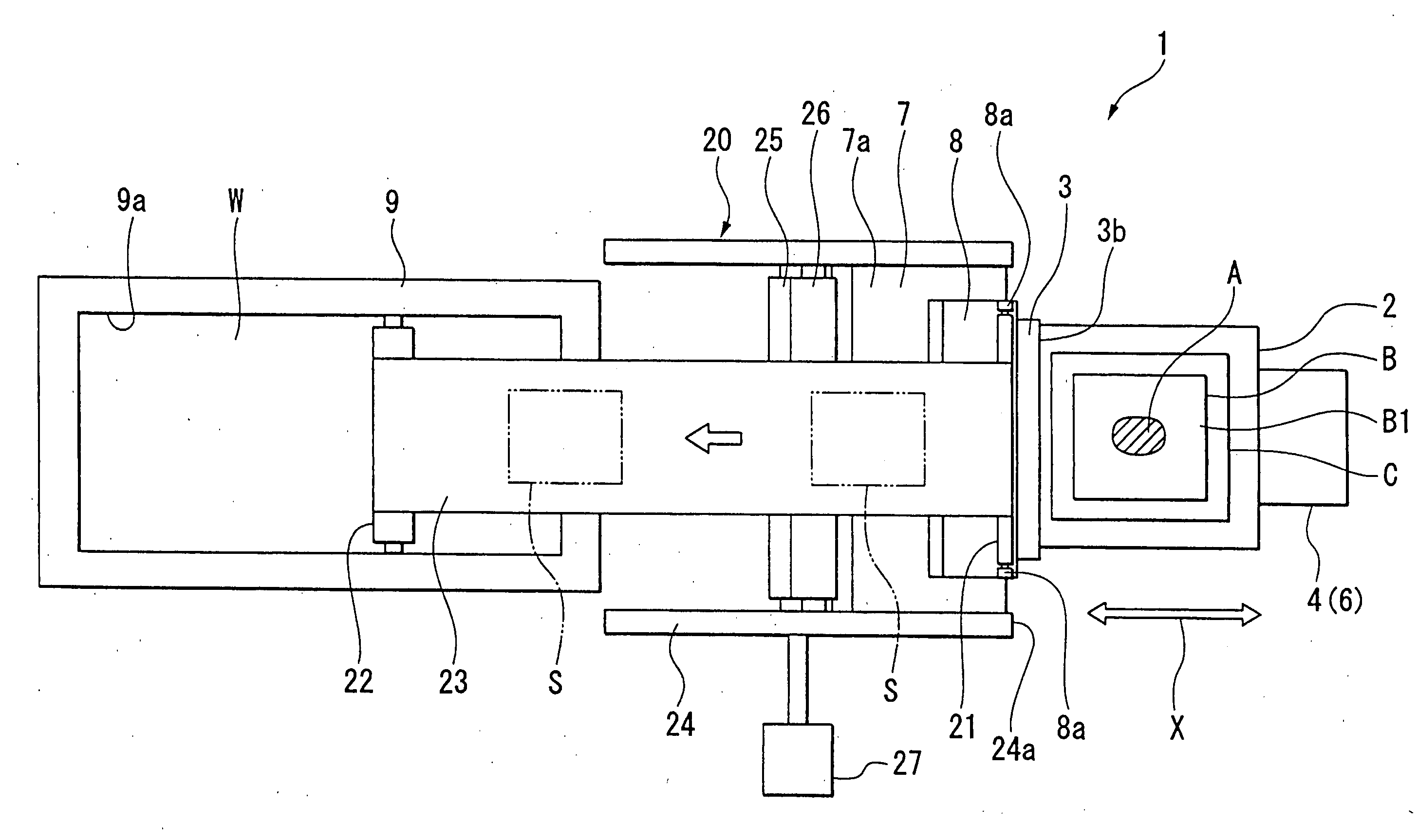
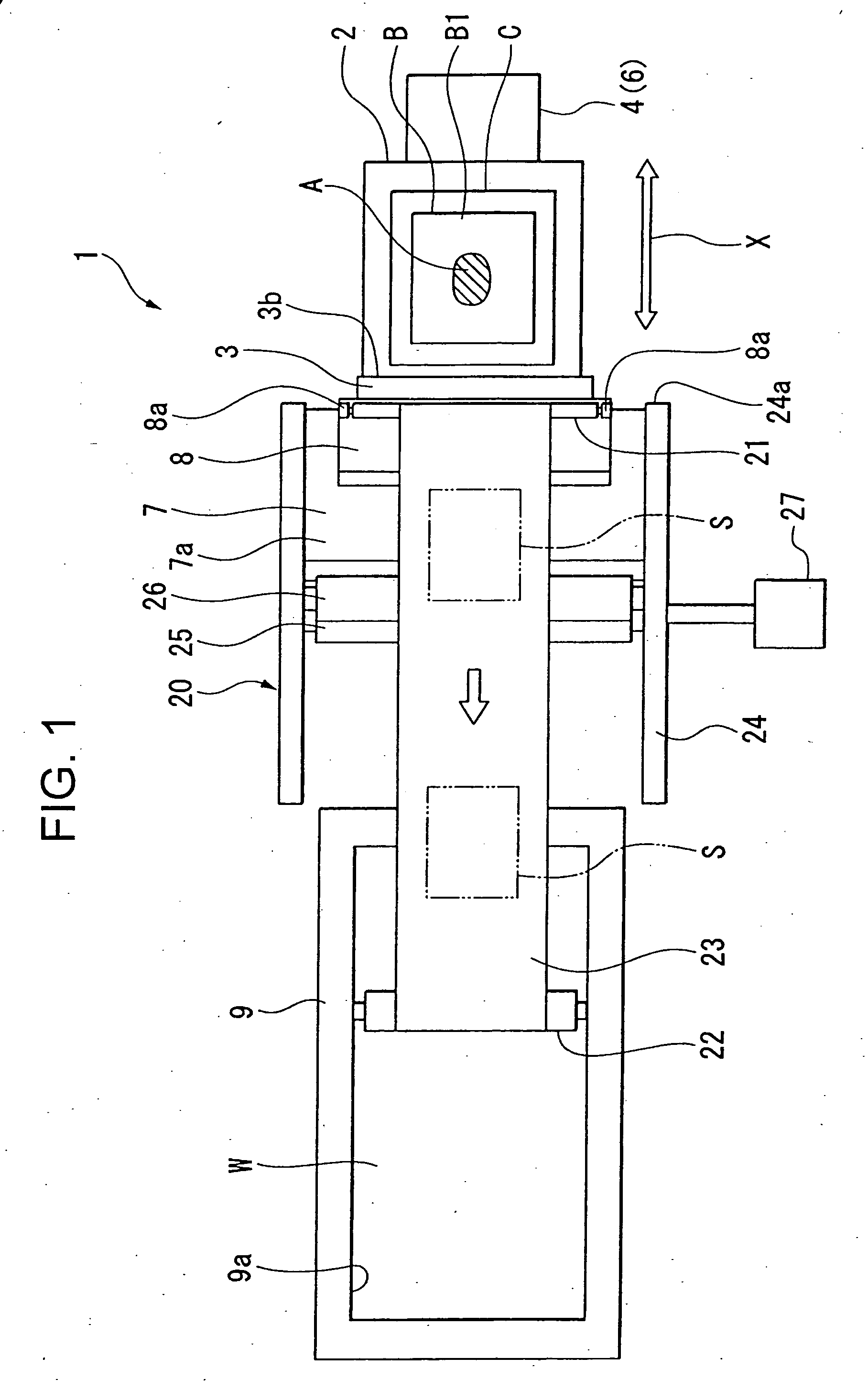
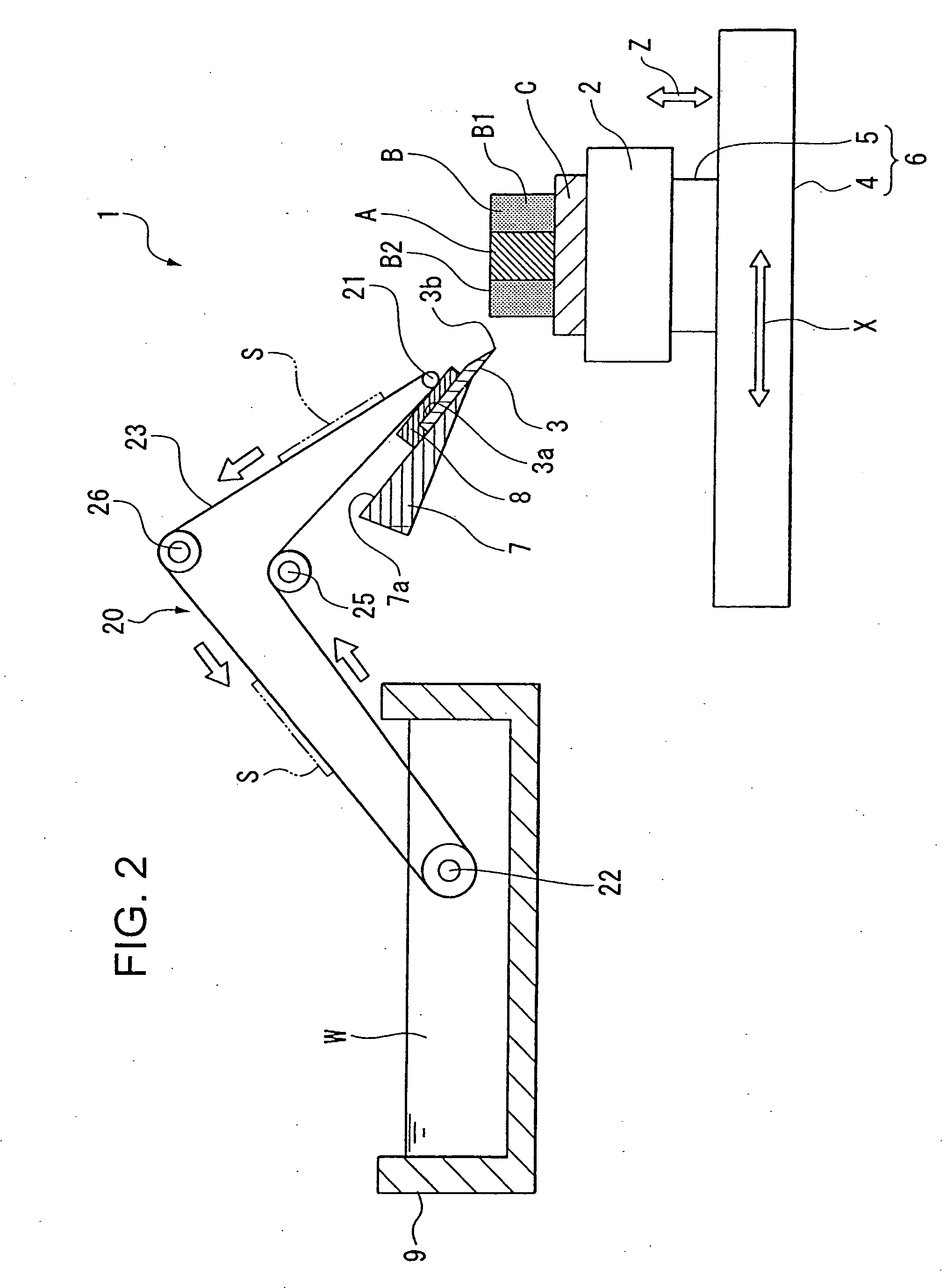
[0040]FIG. 1 and FIG. 2 show a first embodiment according to the invention. A sectioning instrument 1 shown in FIG. 1 is an apparatus for fabricating an extremely thin section having a thickness of 3 through 5 μm from an embedded block B embedded with a living body sample A, sectioning a section from the embedded block B and carrying the section to a next step automatically in a procedure of inspecting and observing the living body sample A included in section. The living body sample A is, for example, a tissue of an organ or the like taken out from the human body, an experimental animal or the like and is pertinently selected in a medical field, a drug field, a food field, or a biological field. Further, the embedded block B is constituted by enveloping the living body sample A by an embedding medium B1, that is, covering to harden a surrounding thereof. Further in details, such an embedded block B is fabricated as follows. First, protein constituting the living body sample A is fi...

second embodiment

[0048]FIG. 4 shows a second embodiment according to the invention. In the embodiment, members common to members used in the above-described embodiment are attached with the same notations and an explanation thereof will be omitted.

[0049] As shown by FIG. 4, according to a sectioning instrument 30 of the embodiment, a blower 31 constituting blowing means is provided at a position of being opposed to the direction switching roller 21 frontward from the cutter 3. Further, the blower 31 can press the endless belt 23 folded back by the direction switching roller 21 to the section S by blowing wind to the section S sliced by the cutter 3. Therefore, the fabricated section S is mounted on the endless belt 23 further firmly and is carried to the rear side of the cutter 3 by the endless belt 23. Particularly, although there is a case in which in sectioning by the cutter 3, the section is curled to a front side of the cutter 3 as in a section S′, the section can be prevented from being curle...

third embodiment

[0050]FIG. 5 and FIG. 6 show a third embodiment according to the invention. According to the embodiment, members common to members used in the above-described embodiments are attached with the same notations and an explanation thereof will be omitted.

[0051] As shown by FIG. 5, according to a sectioning instrument 40 of the embodiment, the direction of the cut blade 3b of the cutter 3 is provided by including a draw angle θ relative to an axis line L orthogonal to feed direction X of the feed mechanism 6 on a cut face formed by the cutter 3. Further, as shown by FIG. 5 and FIG. 6, carrying means 41 includes a belt 42, a supply roller 43 wound with the belt 42 for supplying the belt 42, middle rollers 44, 45 provided on the rear side of the cutter 3, and a rear roller 46 for winding the belt 42. Further, the supply roller 43 is axially attached rotatably to a frame 47, and a supply direction P for supplying the belt 42 from the supply roller 43 to the direction switching roller 21 is...


PUM

PropertyMeasurementUnit
Lengthaaaaaaaaaa
Angleaaaaaaaaaa
Speedaaaaaaaaaa

Abstract

To provide a sectioning instrument capable of fabricating a section having an accurate and uniform thickness to be carried to a next step automatically without deforming a surface of an embedded block and while observing the surface of the embedded block, a sectioning instrument includes a sample base for fixing an embedded block, a cutter for fabricating a section by sectioning the embedded block, carrying means for carrying the section, and a feed mechanism for moving the sample base in a predetermined feed direction, the carrying means includes a belt, a direction switching portion provided on an upper side of the cutter, and a rear roller, the belt is inserted to between the cutter and the direction switching portion from a rear side of the cutter, folded back to an upper side by the direction switching portion and is reeled back to the rear side of the cutter by the rear roller substantially in parallel with the feed direction of the feed mechanism in a plane view thereof.

Description

[0001] This application claims priority under 35 U.S.C. § 119 to Japanese Patent Application No. JP2005-377722 filed Dec. 28, 2005, the entire content of which is hereby incorporated by reference. BACKGROUND OF THE INVENTION [0002] 1. Field of the Invention [0003] The present invention relates to a sectioning instrument for fabricating a section by sectioning an embedded block embedded with a living body sample sampled from the human body, an experimental animal or the like and carrying the fabricated section to a next step. [0004] 2. Description of the Related Arts [0005] In a related art, there is known a method of sectioning an embedded block embedded with a living body sample by an embedding medium to a section having a thickness as extremely thin as several μm, thereafter, observing a sample constituted by dissolving the embedding medium as one of methods of inspecting and observing the living body sample sampled from the human body, an experimental animal or the like. As detai...

Claims


Application Information

Patent Timeline
IPC IPC(8): B26D1/00B26D5/08
CPCG01N1/06Y10T83/2194Y10T83/9454Y10T83/869Y10T83/929Y10T83/2098
Inventor MIYATANI, TATSUYAITO, TETSUMASAFUJIWARA, HIROHITOFUJIMOTO, KOJI
Owner SAKURA FINETEK JAPAN
Learn More