Split-cycle air hybrid engine

a hybrid engine and split-cycle technology, applied in the direction of combustion engines, hot gas positive displacement engine plants, machines/engines, etc., can solve the problems of inability to optimize easily, complex valve/drive train systems, and sacrifice to compressor mode efficiency

Inactive Publication Date: 2007-07-12
SKADERI GRUP LLC
View PDF10 Cites 133 Cited by
  • Summary
  • Abstract
  • Description
  • Claims
  • Application Information

AI Technical Summary

Benefits of technology

[0023] The present invention combines the features of the split cycle engine with the air reservoir of the air hybrid concept and various simplified control features to provide novel arrangements for operation and control of the resulting hybrid engine embodiments. A distinct advantage of the invention is that two or more engine modes as described herein can be operated simultaneously (i.e., in parallel), because the split-cycle engine includes dedicated compression and power pistons.
[0024] Taken as a broad concept, a split-cycle air hybrid engine according to the invention preferably includes:
[0026] a power piston slidably received within a power cylinder and operatively connected to the crankshaft such that the power piston reciprocates through an expansion (or power) stroke and an exhaust stroke during a single rotation of the crankshaft;
[0027] a compression piston slidably received within a compression cylinder and operatively connected to the crankshaft such that the compression piston reciprocates through an intake stroke and a compression stroke during a single rotation of the crankshaft, the compression cylinder being selectively controllable to place the compression piston in a compression mode or an idle mode;
[0028] an air reservoir operatively connected between the compression cylinder and the power cylinder and selectively operable to receive compressed air from the compression cylinder and to deliver compressed air to the power cylinder for use in transmitting power to the crankshaft during engine operation; and
[0029] valves selectively controlling gas flow into and out of the compression and power cylinders and the air reservoir.

Problems solved by technology

However, the prior art appears to involve only adapting a conventional four stroke cycle engine to perform the compression, combustion and motoring functions in a single cylinder.
Problematically, in order to switch among the CB, AM and ICE modes, the valve / drive train system becomes complex, costly and hard to control or maintain.
Additionally, since each cylinder must perform all of the functions for each mode, they cannot be optimized easily.
Accordingly, due to the tolerances and materials required to withstand the heat of combustion, some sacrifice must be made to the efficiency of the compressor mode.
Another problem with performing all functions for each mode (ICE, CB and AM) in every cylinder is that no two modes can be performed in parallel (i.e. simultaneously).
Because prior art air hybrid systems utilize conventional engines, they are restricted to operating in each mode serially, which imposes inherent limitations on their capabilities.
For example, because the CB mode cannot be utilized when the engine is operating as an internal combustion engine (in ICE mode), the air reservoir can only be charged during the braking function of a moving vehicle.
This limitation leads to problems in maintaining the stored charge in the air reservoir.
Additionally, this limitation also means that prior art air hybrid systems are only applicable to moving vehicles, and are not practical for stationary applications such as stationary generators.

Method used


Image

  • Split-cycle air hybrid engine
  • Split-cycle air hybrid engine
  • Split-cycle air hybrid engine

Examples


first embodiment

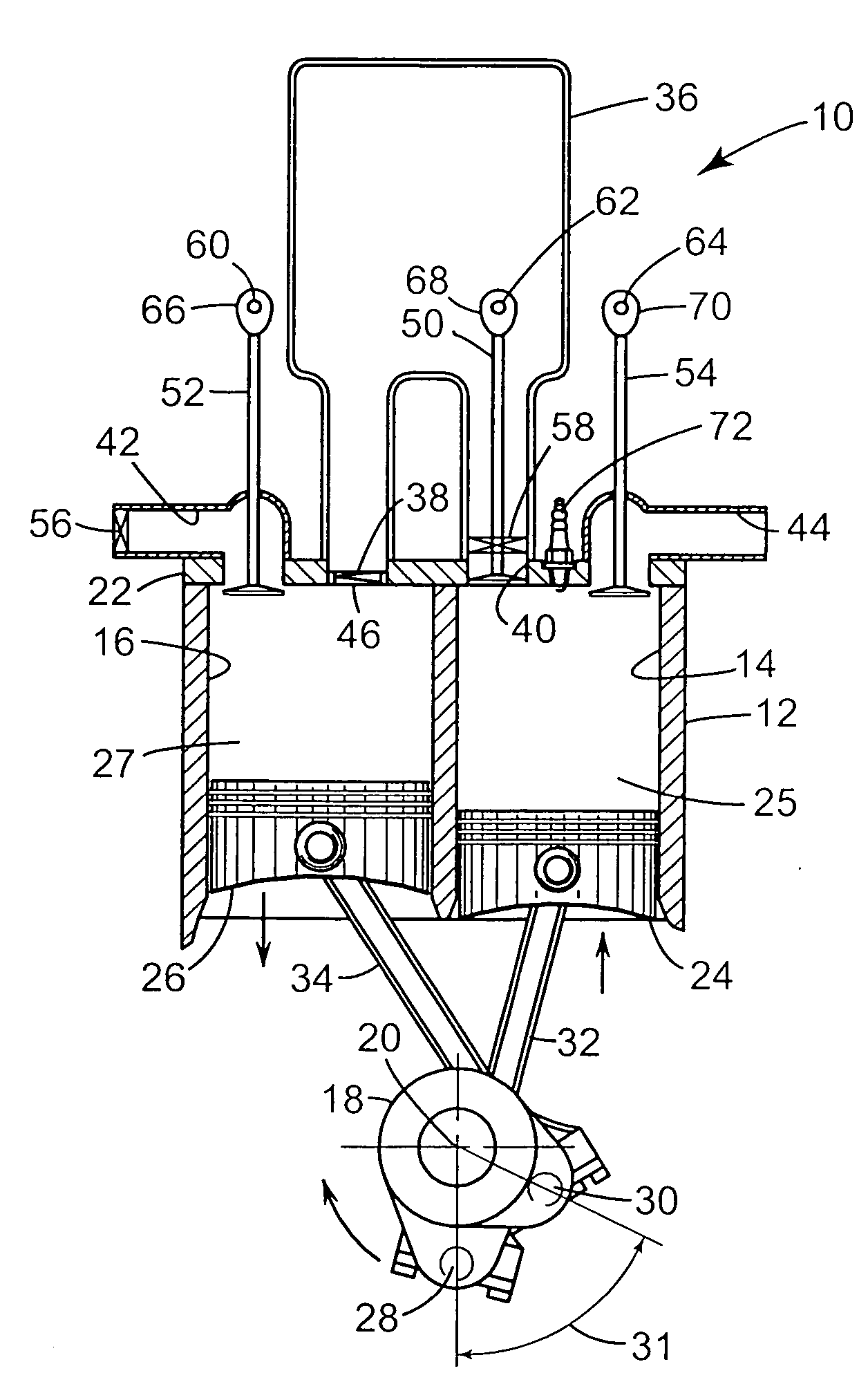
[0058] The cylinder head 22 includes any of various passages, ports and valves suitable for accomplishing the desired purposes of the split-cycle air hybrid engine 10. In the illustrated first embodiment, the gas passage / pressure chamber of the previously mentioned patents is replaced by a much larger air reservoir 36 connected to the head 22 through a reservoir inlet port 38 opening into the closed end of the second cylinder 16 and a reservoir outlet port 40 opening into the closed end of the first cylinder 14. As opposed to a smaller gas passage of a type exemplified in the Scuderi patents, the air reservoir 36 is sized to receive and store compressed air energy from a plurality of compression strokes of the compression piston 26. The second cylinder 16 also connects with a conventional intake port 42 and the first cylinder 14 also connects with a conventional exhaust port 44.

[0059] Valves in the cylinder head 22, which are similar to valves of the engine in the Scuderi patents, i...

second embodiment

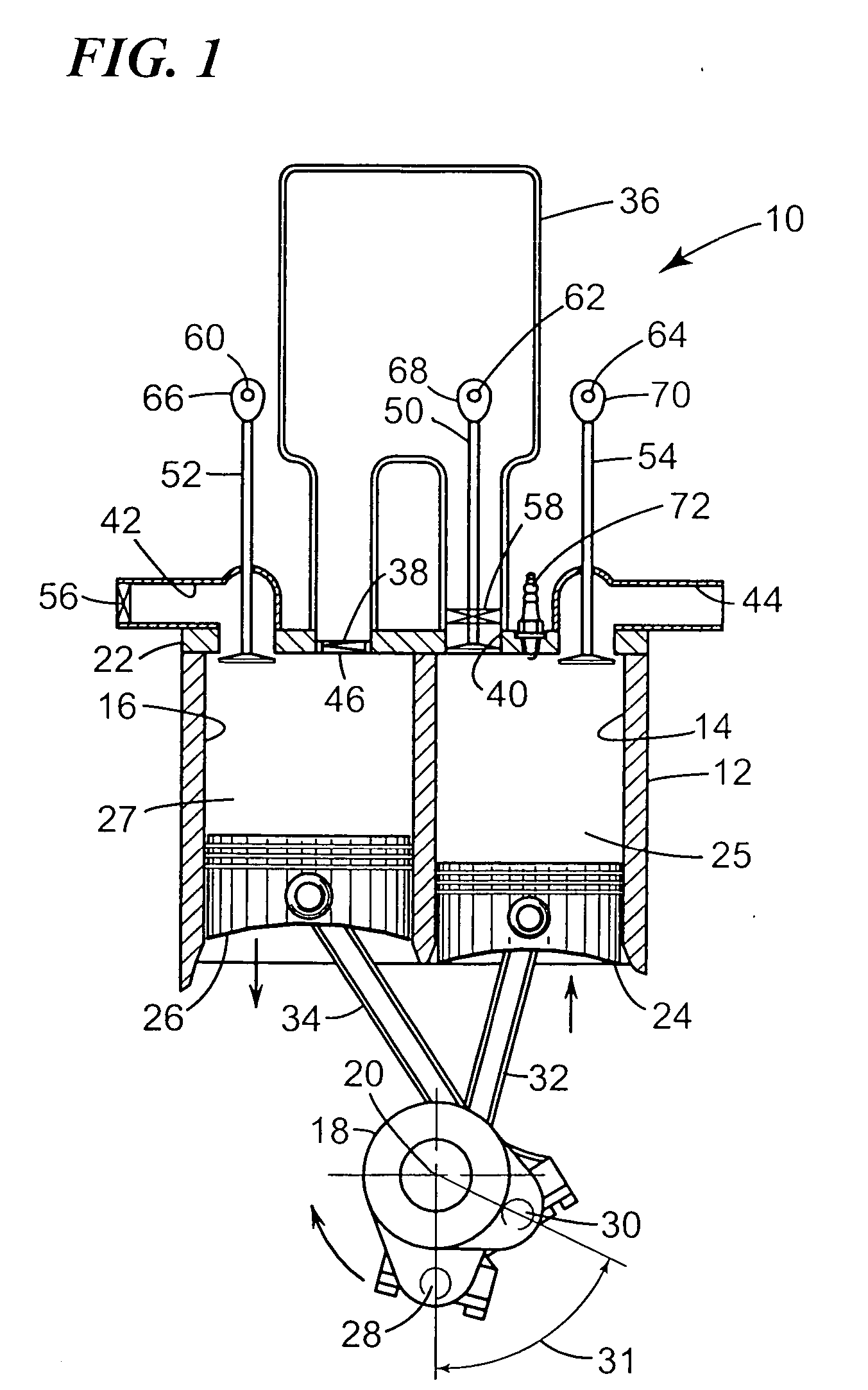
[0064] Referring to FIG. 2, s second embodiment of engine 74 is disclosed wherein like reference numerals indicate like parts. Engine 74 is generally similar to engine 10, but differs in that a small volume crossover (or gas) passage 76 is connected between the inlet port 38 and inlet check valve 46 at one end and the outlet port 40 and outlet valve 50 at an opposite end. This crossover passage 76 extends between the compression chamber 27 in the second cylinder 16 and the combustion chamber 25 in the first cylinder 14 and is similar to the crossover passage in the prior Scuderi patents. As opposed to an air reservoir, this crossover passage 76 is not sized to store a substantial amount of compressed air energy for later use. Rather the passage 76 is typically designed to be as small as practically possible for the most efficient transfer of compressed gas during the ICE mode of the engine 74.

[0065] In an additional modification, separate air reservoir 36 is connected through a rese...

third embodiment

[0066] Referring now to FIG. 3 of the drawings, engine 80 is disclosed, which differs from engine 74 in FIG. 3, only in the addition of a third solenoid valve 82. Valve 82 is located in the runner 78 at its junction with the crossover passage 76 to cut off the connection of the air reservoir 36 with the crossover passage when desired.

[0067] By isolating the air reservoir 36 via valve 82, the overall engine 80 performance can be more effectively optimized during the ICE mode of operation. For example, during the ICE mode all compressed air can be made to flow through the crossover passage 76. Accordingly, the crossover passage 76 can be designed for the most efficient transfer of gas without interacting with the air reservoir. Additionally valve 82 can also be utilized as a throttling valve for part load conditions during the PAP mode.


PUM


Abstract

A split-cycle air hybrid engine operatively connects an air reservoir to a split cycle engine. A power piston is received within a power cylinder and operatively connected to a crankshaft such that the power piston reciprocates through an expansion stroke and an exhaust stroke during a single revolution of the crankshaft. A compression piston is received within a compression cylinder and operatively connected to the crankshaft such that the compression piston reciprocates through an intake stroke and a compression stroke in a single rotation of the crankshaft. The compression cylinder is selectively controllable to place the compression piston in a compression mode or an idle mode. An air reservoir is operatively connected between the compression cylinder and the power cylinder and selectively operable to receive compressed air from the compression cylinder and to deliver compressed air to the power cylinder for use in transmitting power to the crankshaft during engine operation.

Description

TECHNICAL FIELD [0001] This invention relates to split-cycle engines and, more particularly, to such an engine incorporating an air hybrid system. BACKGROUND OF THE INVENTION [0002] The term split-cycle engine as used in the present application may not have yet received a fixed meaning commonly known to those skilled in the engine art. Accordingly, for purposes of clarity, the following definition is offered for the term split-cycle engine as may be applied to engines disclosed in the prior art and as referred to in the present application. [0003] A split-cycle engine as referred to herein comprises: [0004] a crankshaft rotatable about a crankshaft axis; [0005] a power piston slidably received within a power cylinder and operatively connected to the crankshaft such that the power piston reciprocates through a power (or expansion) stroke and an exhaust stroke during a single rotation of the crankshaft; [0006] a compression piston slidably received within a compression cylinder and op...

Claims


Application Information

Patent Timeline
Patent Type & Authority Applications(United States)
IPC IPC(8): F02B33/22
CPCF02B21/00F02B29/00Y02T10/146F02B75/021F02D17/026F02B33/22F02B41/06Y02T10/12F02B75/00F02G1/00
Inventor SCUDERI, SALVATORE C.SCUDERI, STEPHEN P.
Owner SKADERI GRUP LLC
Why Eureka
Try Eureka