Processing apparatus

a technology of processing apparatus and processing chamber, which is applied in the direction of coating, chemical vapor deposition coating, metallic material coating process, etc., can solve the problems of unfavorable temperature control, unfavorable maintenance work, and unnecessary thin film peeling, etc., to achieve speedy and easy maintenance such as cleaning work, the effect of superior temperature controllability

Inactive Publication Date: 2007-07-12
TOKYO ELECTRON LTD
View PDF5 Cites 390 Cited by
  • Summary
  • Abstract
  • Description
  • Claims
  • Application Information

AI Technical Summary

Benefits of technology

[0009] An object of the present invention is to provide a processing apparatus including a shower head structure having a gas injecting surface superior in temperature controllability. Another object of the present invention is to provide a processing apparatus, in which only a component part having a gas injecting surface among component parts of a shower head structure can be independently separated from the other component parts, and thus, maintenance such as a cleaning work can be speedily carried out with ease.

Problems solved by technology

As a result, an unnecessary film may possibly adhere to the gas injecting surface.
Such unnecessary thin films will peel off to be in particles, if they are left unattended.
Thus, the maintenance work is very complicated and time-consuming.

Method used


Image

  • Processing apparatus
  • Processing apparatus
  • Processing apparatus

Examples


first embodiment

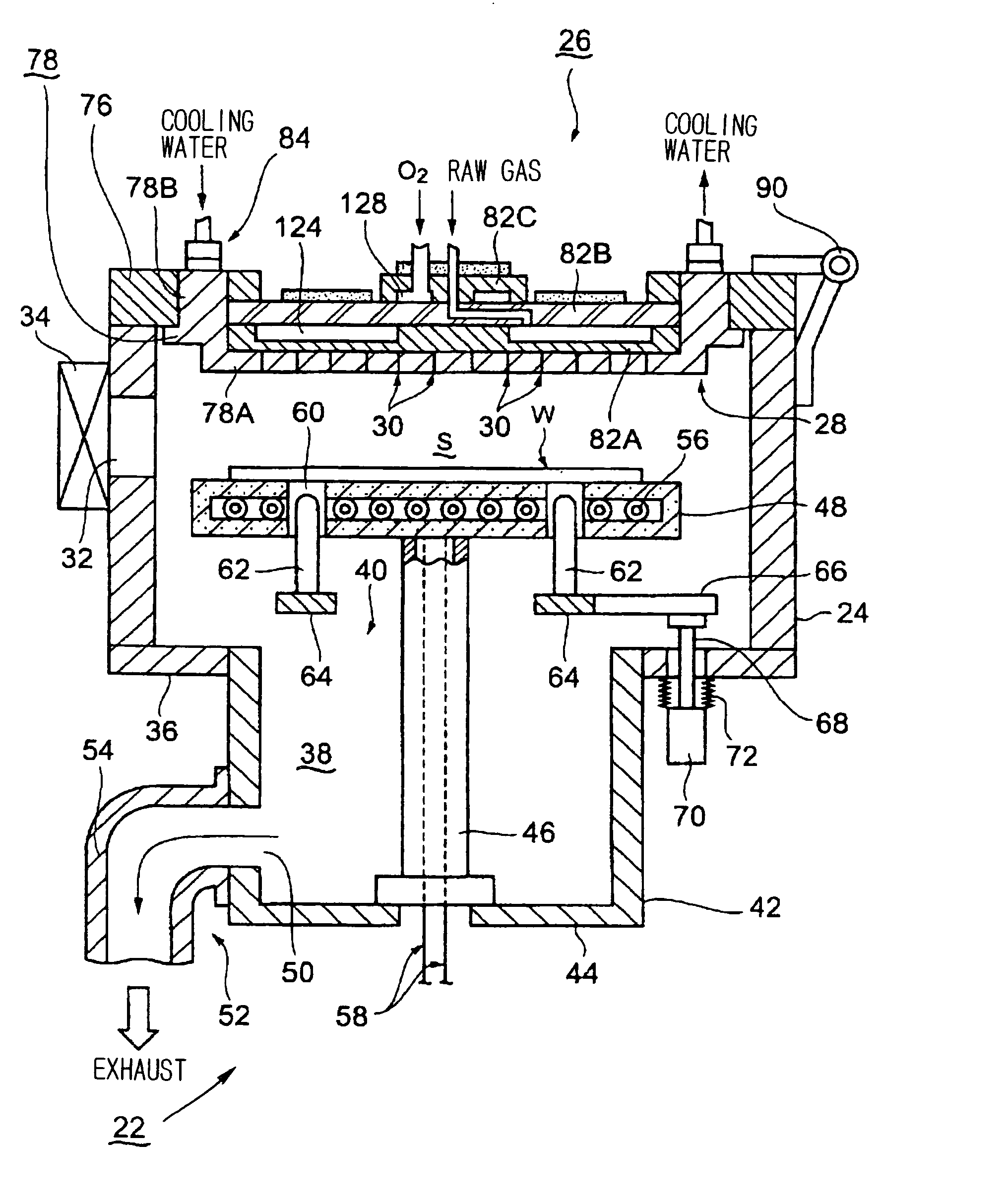
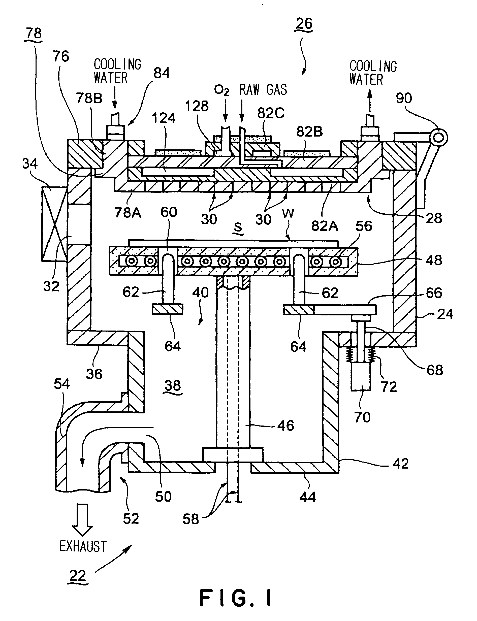
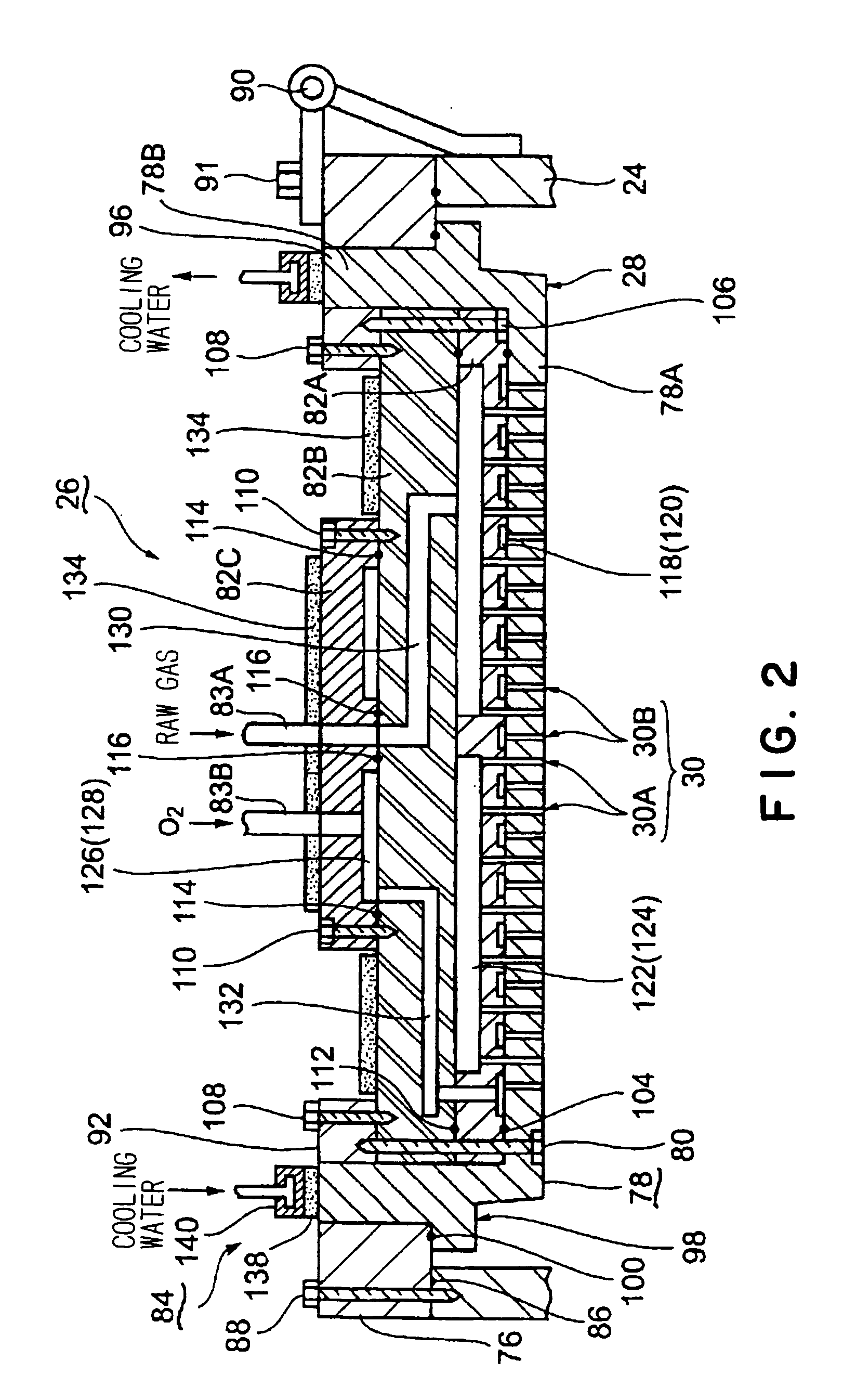
[0024] First, a first embodiment will be described with reference to FIGS. 1 to 4. A film forming apparatus 22 includes a processing vessel 24 of a substantially cylindrical shape, which has an opened ceiling portion and is made of aluminum. A shower head structure 26 is arranged on the ceiling portion of the processing vessel 24 to supply process gases for film deposition such as a raw gas and oxidizing gas into the processing vessel 24. A number of gas injection ports 30 are formed in the lower surface, or a gas injecting surface 28, of the shower head structure 26. The process gases are injected toward a processing space S through the gas injection ports 30. The detail of the shower head structure 26 will be described later.

[0025] Formed in the circumferential side wall of the processing vessel 24A is a carrying-in-and-out port 32, through which a semiconductor wafer W, or a process object, is transferred to and from the processing vessel 24. The carrying-in-and-out port 32 can ...

second embodiment

[0045] Next, the second embodiment of the present invention will be described with reference to FIGS. 5 and 6. A shower head structure in the second embodiment is different from that in the first embodiment in that the former is configured such that it is not possible to remove only a shower head main body from the shower head structure; but shower head structure in the second embodiment is similar to that in the first embodiment in that the former is also configured such that its shower head main body can be efficiently cooled. In FIGS. 5 and 6, the same component parts as those shown in FIGS. 1 to 4 are designated by the same reference numerals, and therefore, a duplicated explanation will be omitted below. In the second embodiment, a ring-shaped sealing flange 152 projecting outward and extending in a circumferential direction is provided at an outer circumferential surface of an upper portion of a side wall 78B of a shower head main body 78. An engaging step 154 is formed on an ...


PUM

PropertyMeasurementUnit
angleaaaaaaaaaa
angleaaaaaaaaaa
shapeaaaaaaaaaa

Abstract

A shower head structure (26) includes a shower head main body (78) of a one-piece structure formed in a generally cup shape and having a bottom wall (78A) provided with a plurality of gas injection holes (30A, 30B) formed therein and a side wall (78B) rising from a peripheral portion of the bottom wall. A plurality of gas diffusion chamber forming plates (82A-82C) are housed in the shower head main body (78). A through-hole is formed in a head mounting frame (76) disposed on a ceiling of a processing vessel (24). An upper portion of the side wall (78B) of the shower head main body (78) is inserted into the through-hole, so that a part of the side wall (78B) is exposed to the exterior of the processing vessel. A cooling mechanism (84) is disposed at the upper end portion of the side wall (78B). Heat transfer between the cooling mechanism (84) and the bottom wall (78A) is enhanced, so that the temperature of the bottom wall (78A) can be controlled at a proper value, thereby preventing any adhesion of an unnecessary film onto the bottom wall (78A).

Description

TECHNICAL FIELD [0001] The present invention relates to a processing apparatus that processes a process object such as a semiconductor wafer by a predetermined process, for example, a thermal process for film deposition. BACKGROUND ART [0002] In general, various kinds of processes, such as a film forming process, an etching process, a thermal process, a modifying process and a crystallizing process, are repeatedly performed to a process object such as a semiconductor wafer in order to fabricate a semiconductor integrated circuit. When each of the various kinds of processes is performed, process gases required for the process are supplied into a processing vessel. JP 10-321613A discloses one example of an apparatus that performs a film forming process out of the foregoing processes. This film forming apparatus has a shower head structure disposed on a ceiling portion of a processing vessel which can be evacuated. A raw gas and a support gas such as an oxidizing gas or a reducing gas ...

Claims


Application Information

Patent Timeline
Patent Type & Authority Applications(United States)
IPC IPC(8): C23F1/00C23C16/00C23C16/44C23C16/455H01L21/00H01L21/31
CPCC23C16/455H01L21/67109C23C16/45572C23C16/45565
Inventor AMIKURA, MANABU
Owner TOKYO ELECTRON LTD
Why Eureka
Try Eureka