External flue heat exchangers

a heat exchanger and external flue technology, applied in the field of heat exchangers, can solve the problems of not revealing the hollow heat conductive tubing enclosed within a substantially dry cavity, and achieve the effects of convenient installation, convenient packaging, and reduced cos

Inactive Publication Date: 2007-07-12
FERRARO JOSEPH C
View PDF7 Cites 16 Cited by
  • Summary
  • Abstract
  • Description
  • Claims
  • Application Information

AI Technical Summary

Benefits of technology

[0019] It is therefore an object of the present invention to provide a heater exchanger for domestic hot water with ease of installation, maintenance and removal.

Problems solved by technology

It does not disclose a coil of hollow heat conductive tubing enclosed within a substantially dry cavity.

Method used


Image

  • External flue heat exchangers
  • External flue heat exchangers
  • External flue heat exchangers

Examples


Embodiment Construction

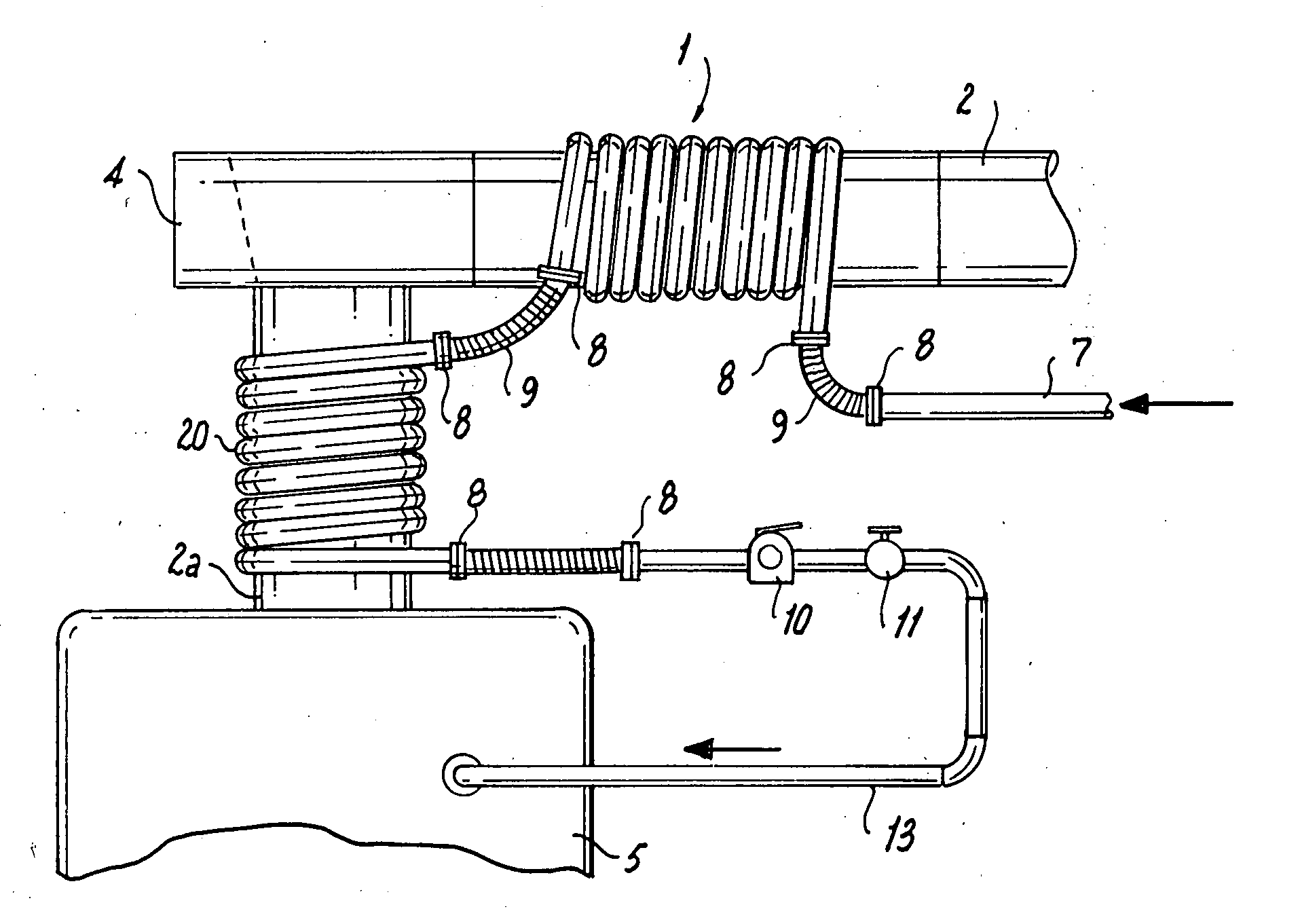
[0057] For ease of installation, maintenance, and removal, the heat exchangers of this invention are mounted external to a section of flue pipe or are an integral part of a section of flue pipe.

[0058] Although the primary application is the preheating of a domestic hot water supply, a secondary application is the boosting of return water temperature in a hydronic heating installation prior to reentry to the furnace coil. In either case, the objectives are to reduce fuel use and to reduce pollution and wear of the furnace and burner.

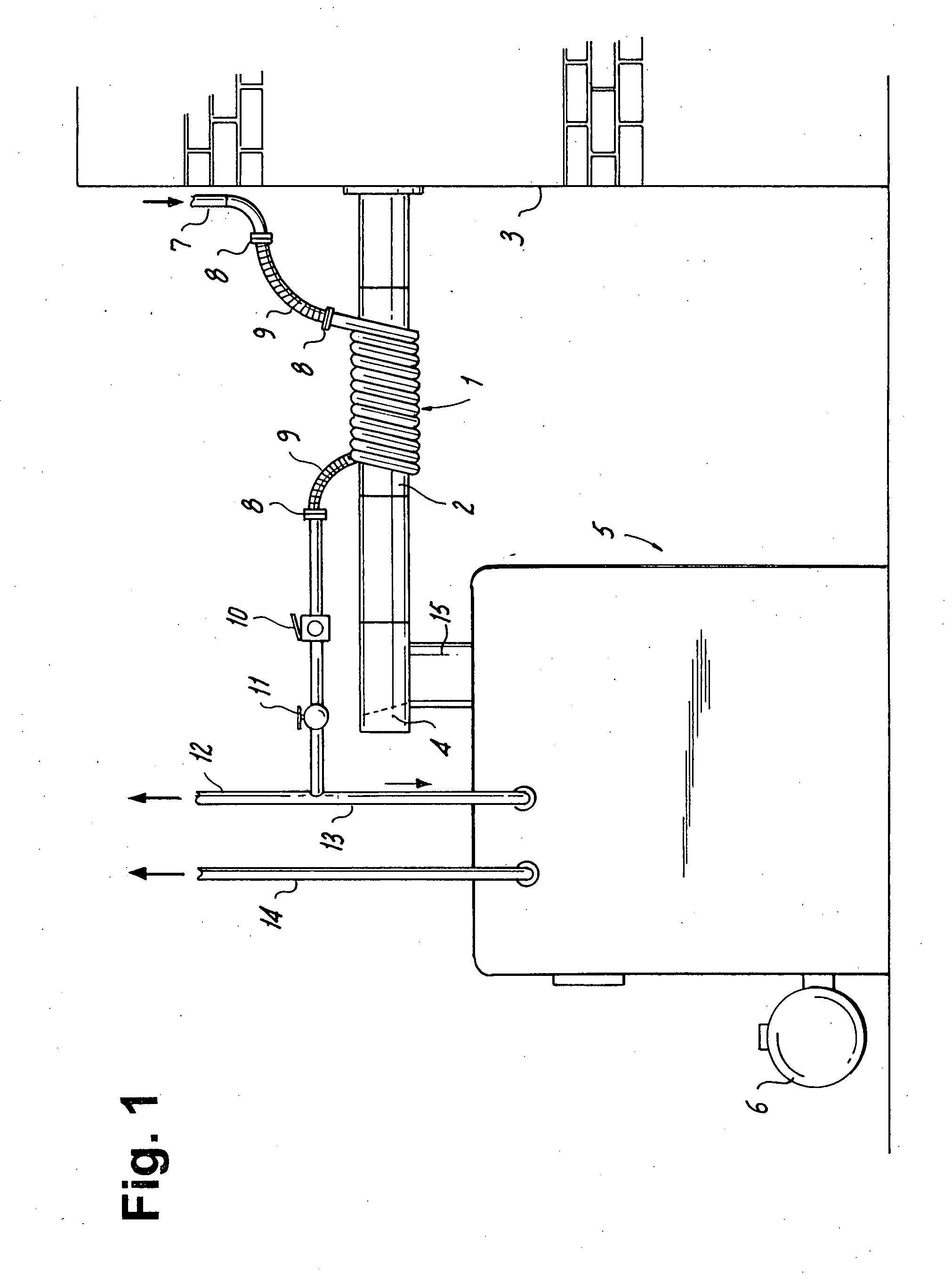
[0059]FIG. 1 shows a typical installation showing an oil or gas burner 6 on a furnace or boiler 5 with flue pipe section 2 leading to masonry chimney 3. A short vertical flue section 15 leads to a draft regulating damper 4. The flue heat exchanger 1 includes a coil of heat conductive tubing, such as copper tubing, which is wrapped around flue section 2. Flue heat exchanger picks up heat from the heated flue gasses within flue section 2. The cold water s...


PUM


Abstract

A heat exchanger is mounted external to a section of flue pipe or is an integral part of a section of flue pipe. The heat exchanger preheats a domestic hot water supply and boosts the return water temperature prior to reentry to the furnace coil. The heat exchanger reduces fuel use, pollution and wear of the furnace and burner. A typical heat exchanger installation includes an oil or gas burner located on a furnace or boiler having a flue pipe leading to a gaseous outlet, such as a masonry chimney. A short vertical flue section leads to a draft-regulating damper. The flue heat exchanger may be a coil of tubing wrapped around flue section, such that the tubing picks up heat from the heated flue gasses. Preheated water exits from the heat exchanger.

Description

RELATED APPLICATIONS [0001] This application is a continuation of currently pending U.S. patent application Ser. No. 10 / 842,067, filed May 10, 2004, which application is a continuation of U.S. patent application Ser. No. 10 / 046, 013, filed Jan. 11, 2002, now U.S. Pat. No. 6,749,014, issued Jun. 15, 2004, which was a continuation-in-part of application Ser. No. 09 / 404,073, filed Sep. 23, 1999.FIELD OF THE INVENTION [0002] The present invention relates to heat exchangers, which are mounted external to a section of flue pipe or are an integral part of a section of flue pipe. BACKGROUND OF THE INVENTION [0003] Heat exchangers are known, which direct water in a pipe through a flue. [0004] U.S. Pat. No. 4,122,801 of Burns describes a heat exchanger which first encircles water pipes in 2 circular rings around an exhaust flue, but then directs the water into coils within the exhaust flue. The external rings appear to be for positioning the water flow headers equally around the flue, not to ...

Claims


Application Information

Patent Timeline
Patent Type & Authority Applications(United States)
IPC IPC(8): F24H3/00F24B9/00F24D12/02F28D1/06F28D21/00
CPCF24B9/006F24D12/02F24D2200/04F24D2200/18F28D7/0016F28D21/0007Y02B10/70Y02B30/14F28D1/06Y02B30/00
Inventor FERRARO, JOSEPH C.
Owner FERRARO JOSEPH C
Why Eureka
Try Eureka